TFUNIPAYLOAD01 – Universal MAVLink Sensor Interface for UAV Payloads
TFUNIPAYLOAD01 is a universal interface board designed for seamless integration of custom sensors with PX4- or ArduPilot-based UAVs, especially when no dedicated driver for the sensor exists in the flight stack.

Its key advantage lies in the use of MAVLink Tunnel packets, eliminating the need to modify autopilot firmware. This solution is suited for rapid deployment and testing of new environmental or scientific sensors without the need to delve into autopilot firmware development. It provides a plug-and-play bridge between your sensor and the powerful TF-ATMON ecosystem.
Intended Use Case
TFUNIPAYLOAD01 is intended for users developing or deploying atmospheric or scientific sensors where direct driver support in PX4/ArduPilot is not yet available or practical. Common use cases include:
- Experimental sensors under development
- Rare or proprietary measurement devices
- Quick integration of simple payloads without altering autopilot/flight stack code
The example of expected approach is the TFPM01 airborne particulate matter sensor or AIRDOS03 radiation sensor. The hardware platform provides:
- 128 kB Flash and 16 kB RAM – sufficient for MAVLink message handling
- Multiple UARTs for communication with both sensors,GNSS receiver, and the flight controller
- Standard MLAB form factor is used for mechanical and electrical compatibility with peripheral and sensor modules
Hardware Overview
The TFUNIPAYLOAD01 module is based on the MLAB ATmegaTQ4401 board equipped with an ATmega1284P microcontroller.
| Parameter | Value | Description |
|---|---|---|
| Main Microcontroller (MCU) | ATmega1284P | 128 kB Flash, 16 kB RAM |
| I2C Connector | 4-pin JST-GH | Pixhawk standard |
| FMU Communication Port | 1x TELEM/UART | Main data input and output |
| Operating Voltage | 5V (nominal), supported range 4.5-5.5V | Power supplied via UART Peripheral port, Protected overvoltage and reverse polarity |
| Power Consumption | Dependent on connected devices | Current consumption varies based on attached payload 200mA expected maximum |
| Operating Temperature | −20°C to +50°C | |
| Mass | 25g (PCB) | Mass of cabling needs to be added |
| Dimensions | 70.61x50.29 mm (PCB) / Custom case dimensions | Refer to case drawings |
| MAVLink Communication Protocol | MAVLink Tunnel over UART | No need for autopilot firmware modification |
| Time Synchronization (PPS) | Yes, via external GPS (TFGPS01) | Syncs to GPS pulse signals |
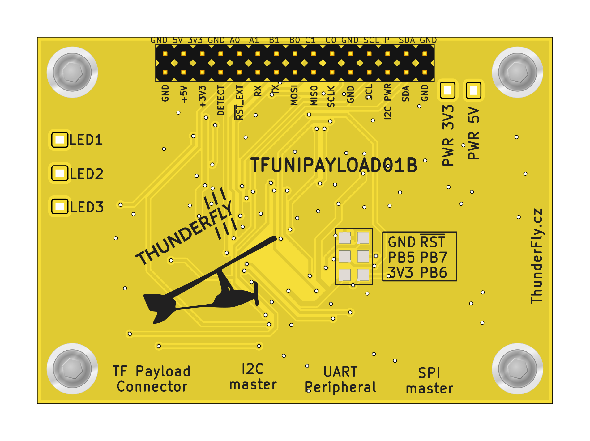
Connector Pinout
TFUNIPAYLOAD01 provides a TELEM/UART port for connection to a flight controller and I2C, SPI, and GPIO for Payload connectivity.
TF Payload connector
This connector is primarily intended for time synchronization with the TFGPS01 GNSS receiver, which provides location and time pulse signals (PPS) on its “Payload Connector”. The device side of the Payload connector has the following pinout. The RX and TX are crossed at the master side (TFGPS).
| Signal | Pixhawk Color | ThunderFly Color |
|---|---|---|
| TIMEPULSE |  Black Black |  Blue Blue |
| EXTINT | Black |  Yellow Yellow |
| GPIO | Black |  White White |
| SDA | Black |  Green Green |
| SCL | Black | Yellow |
| TX | Black | White |
| RX | Black | Green |
| GND | Black | Black |
I2C master
The connector is used for the connection of auxiliary payload sensors. The humidity and temperature sensors are a common example.
| Signal | Pixhawk Color | ThunderFly color |
|---|---|---|
| +5V (out) |  Red Red | Red |
| SCL | Black | Yellow |
| SDA | Black | Green |
| GND | Black |  Black Black |
UART Peripheral
The UART interface is compatible with the Pixhawk connector standard as a peripheral device and enables integration with onboard flight controllers. It is the main power input for TFUNIPAYLOAD01 and connected devices. The 5V input is protected against reverse current from the TFUNIPAYLOAD01 and connected devices.
| Signal | Pixhawk Color | ThunderFly Color |
|---|---|---|
| +5V (in) | Red | Red |
| RX | Black | White |
| TX | Black | Green |
| CTS | Black | Blue |
| RTS | Black | Yellow |
| GND | Black | Black |
SPI master
This SPI master interface should be used for the connection of external sensors or alternative communication devices like TFLORA01.
| Signal | Pixhawk Color | ThunderFly color |
|---|---|---|
| +5V (out) | Red | Red |
| SCK | Black | Yellow |
| MISO | Black | Blue |
| MOSI | Black | Green |
| CS! | Black | White |
| CS2 | Black | Blue |
| GND | Black | Black |
Communication Principle
Sensor data is processed on the TFUNIPAYLOAD01 module using Arduino-compatible firmware. The microcontroller encodes the measurements into MAVLink Tunnel packets, which are:
- Sent over UART to the autopilot’s telemetry port
- Logged automatically by the autopilot (if configured correctly)
- Forwarded to the Ground Control Station (GCS) with software such as QGroundControl or TF-ATMON
The TF-ATMON system is designed to receive and process such sensor data in the form of MAVLink Tunnel messages. This enables the TF-ATMON system to visualize and geolocate the sensor measurements in time and space. This allows users to quickly gain insight into the measured environment without requiring any sensor-specific firmware changes in PX4 or ArduPilot.
Advantages of the MAVLink Tunnel Approach
- No firmware modification of PX4 or ArduPilot is necessary
- Standardized MAVLink interface allows inspection and logging tools (QGC, uLog, MAVSDK)
- Sensor abstraction: Only the TFUNIPAYLOAD01’s firmware knows the sensor-specific protocol and interface
- Flexible and portable: The same approach works across multiple autopilot flight stacks
Integration Workflow
- Connect your sensor to one of the TFUNIPAYLOAD01’s digital or analog interfaces.
- Develop a small Arduino sketch for the ATmega1284P to:
- Read data from the sensor
- Format it as a
MAVLink TUNNELmessage - Send it via serial port to the autopilot
- Wire the TFUNIPAYLOAD01 to an available TELEM port on the Pixhawk or compatible autopilot.
- Configure autopilot parameters (see below) to enable MAVLink message logging in PX4.
PX4 Parameter Configuration
The following PX4 parameters must be set to make TFUNIPAYLOAD01 working (example for TELEM2):
| Parameter | Value | Description |
|---|---|---|
| MAV_1_CONFIG | TELEM 2 | Enable MAVLink on the correct UART port |
| MAV_1_FORWARD | 1 | Enable message forwarding |
| MAV_1_RADIO_CTL | 0 | Disable radio control on that port |
| MAV_1_RATE | 0 B/s | Unlimited rate |
| SER_TEL2_BAUD | 57600 | Baud rate (match your firmware settings) |
Example Firmware
Refer to the TFUNIPAYLOAD_MINIMAL sketch for a lightweight example that sends only HEARTBEAT and TUNNEL messages:
mav.SendTunnelData(data, sizeof(data), sensor_id, 1, 1);
Function Arguments:
data: array of bytes (max 127)length: length of datasensor_id: identifier for your custom sensorsysid: usually1, or0for broadcastcompid: usually1, or0for broadcast
How to Verify MAVLink Message Reception
Using QGroundControl
Ensure your autopilot is connected via a telemetry radio or USB-UART bridge, do not use the flight controller’s USB port directly. The following steps allow you to inspect incoming MAVLink TUNNEL messages:
- Open QGroundControl and connect the autopilot.
- Click the QGC logo (top left corner), navigate to Analyze Tools, then select MAVLink Inspector.
- Look for messages of type
TUNNEL. These confirm correct reception and forwarding.
Note: This requires the messages to be broadcast (sysid = 0, compid = 0), and QGC must be on a MAVLink-enabled link (not applicable for direct USB connection).

Using the PX4 Console
You can verify message reception even without broadcast using the PX4 shell:
- Connect via mavlink_shell.py or through QGroundControl > Analyze Tools > Console.
- Run:
listener mavlink_tunnel -n 100
This command displays the last 100 received tunnel messages.

Using Flight Logs
MAVLink TUNNEL messages are logged in PX4 .ulg logs. Although tools like Flight Review don’t visualize this type of data, you can:
- Use PlotJuggler to load and inspect message content
- Use TFUNIPAYLOAD Log Viewer Notebook to parse tunnel data programmatically
Logging and Monitoring
- Tunnel messages can be monitored using
listener mavlink_tunnelon PX4 - Use QGroundControl with a radio modem to inspect
TUNNELmessages in real time - For post-processing, extract data from
.ulglogs using custom tools or PlotJuggler
Limitations
- Autopilot memory is limited – avoid sending excessive data
- Max 3 MAVLink instances (incl. modem) due to PX4 firmware constraints
- Proper MAVLink stream segregation is necessary for logging vs telemetry transmission