TFI2CADT01 - I²C address translator
TFI2CADT01 is an I2C device address changer. This function allows you to connect multiple I2C devices with the same address to one master device on the same bus.
That is a common problem in case multiple I2C sensors with the same address (or a limited number of addresses) need to be connected to one I2C master. The purpose of this module is to change the address with which the I2C master calls to the address of the target I2C (slave) device. The module is based on LTC4317 I2C address translator IC. The module is designed and optimized for use on Pixhawk-compatible drones, especially UAVs. The design of the module is compatible with the dronecode connectors standard.
How to Buy
- Direct order — Email sale@thunderfly.cz for quotations, customizations, or volume pricing handled directly by ThunderFly s.r.o.
- Purchase TFI2CADT01 on Lectronz for online orders.
Translation function
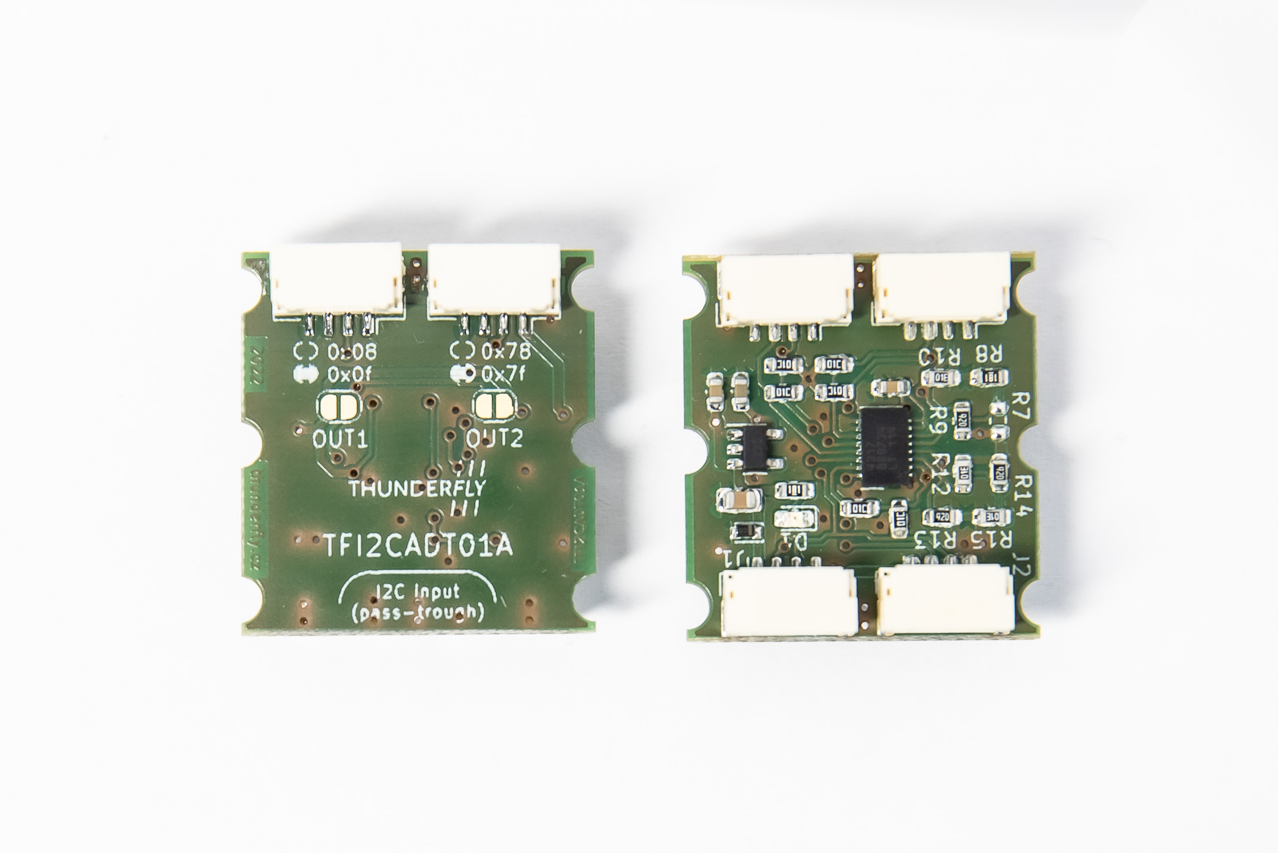
The called address of the slave device is translated by a logical operation XOR with the address bits configured in the TFI2CADT01 module. Each TFI2CADT01 port has a different default address. The address of each port can be changed independently by soldering solder jumpers JP1 and JP2.
NOTE: The TFI2CADT01 is not an I2C buffer, therefore the quality of input bits affects its function, and also corrupted data on input are propagated on the output. The address translator does XOR with the input address clocked in. To avoid related issues with bus data integrity we strongly recommend using ThunderFly’s TFCABI2C cables which minimizes SDA/SCL crosstalks. In some cases, where the I2C network has a significant length or number of nodes the use of TFI2CEXT01, that is I2C extender with buffer function.
Configuration
The default address translation is listed in the following table.
| Port | Solder jumper | XOR value (in hex) | XOR value in binary form |
|---|---|---|---|
| 1 | Disconnected (default) | 0x08 | 0b0001000 |
| 1 | Soldered | 0x0f | 0b0001111 |
| 2 | Disconnected (default) | 0x78 | 0b1111000 |
| 2 | Soldered | 0x7f | 0b1111111 |
The connectors on the top side and the unpopulated connector on the bottom side are identical. There is no address difference between them. That should be used to split the bus to other sensors.
Determining the new address of the I2C device
The new device address which should be called by the master could be calculated by doing XOR with the TFI2CADT01 port address and original device address. The result is the new device address. You can use an online calculator. Another approach is determining the new address heuristically using the i2cdetect command or similar command.
Example of usage
The TFI2CADT01 could be used with a wide variety of ThunderFly or Pixhawk I²C sensors, here are a few examples.
Tachometer (RPM) sensors
The TFI2CADT01 could be easily used for the connection of multiple TFRPM01 tachometer sensors, which is especially useful for multi-rotor airframes.
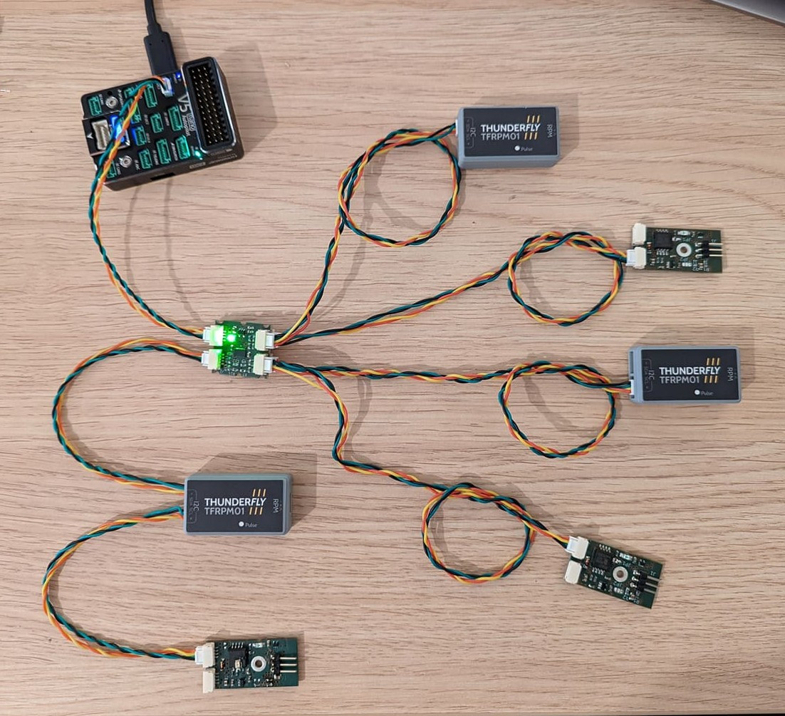
The TFRPM01s without the covers have changed the I2C address by solder jumpers.
Redundant airspeed sensors
The TFI2CADT01 could also fix troubles with the connection of multiple TFSLOT01 airspeed sensors to one bus. It could be used even for other I2C-based airspeed sensors. That could increase the redundancy, in situations where a failure of the sensor is more probable than failure of the bus itself.
Temperature and hygrometer sensors
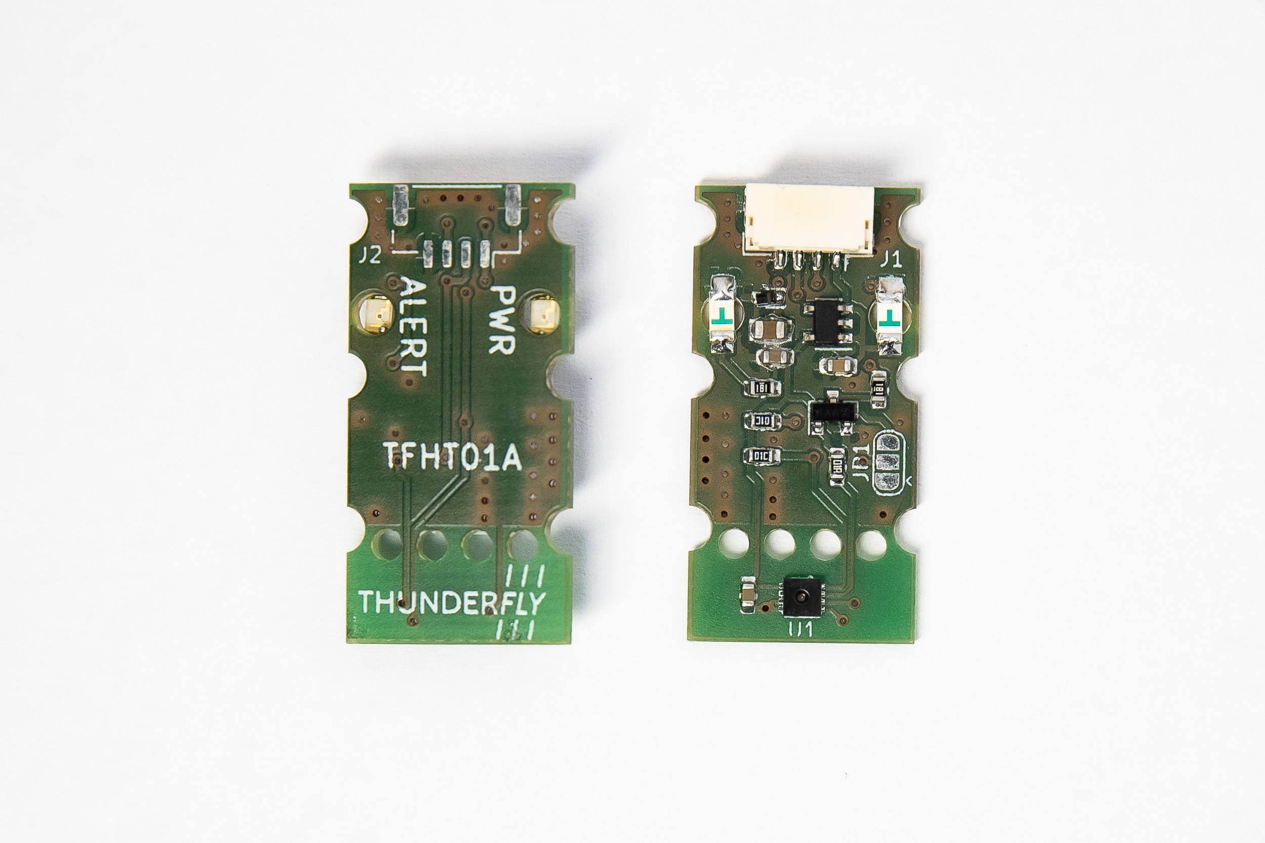
For example the TFHT01 connected by use of TFI2CADT01 allows measuring of temperature and humidity by multiple airframe locations at once.
FAQ
How I can change the I2C addresses used in the Pixhawk to the ones translated by the TFI2CADT01?
The translated addresses might not be recognized by default in the PX4 (that is usually experienced in the case of the SDP3x sensor driver). One approach to solve that is to create a configuration file named config.txt on the SD card as is documented in the PX4 documentation. In this file, you can specify the start commands for the driver of the translated sensors.
Here’s an example of the content of the /etc/config.txt on the SD card:
sdp3x_airspeed start -X -a <translated_address_a>
sdp3x_airspeed start -X -a <translated_address_b>
Replace <translated_address_a> and <translated_address_b> with the actual translated I2C addresses of your sensors. Addresses could be obtained by calculating XOR with the original address. Or it can be obtained with the i2cdetect command.