FAQ
What about the measurement resolution of the RPM?
RPM measurement resolution depends on pooling interval and the number of pulses per revolution.
RPM is calculated from measured values (pulses per interval) as follows
Therefore, the resolution of measured RPM is as follows:
Where:
- N is pulses per revolution
- τ is the pooling interval in seconds
- Nc is pulses counted during the measurement pooling interval
- Res is the absolute resolution of measurement in +/- RPM
Therefore, the absolute resolution of the sensor is independent of the current RPM measured and remains constant depending on sensor configuration; however, relative resolution increases with the RPM measured. The absolute resolution strongly depends on the length of the pooling interval (a longer interval gets better resolution). The resolution also increases with the number of pulses per revolution, where more pulses per revolution give better RPM resolution. Related terms like precision and accuracy are more difficult to analyze because they depend on hardware and firmware versions of Pixhawk, but these errors could be neglected in the usual use cases.
I can’t find the parameter PCF8583_EN or the autopilot reports pcf8583 not found, what should I do?
If you cannot find parameters related to the PCF8583 sensor or if you receive the error nsh: pcf8583 command not found when attempting to run the pcf8583 driver, it likely means that your firmware does not include this driver.
This issue occurs because the PCF8583 driver was disabled in the firmware by the PX4 development team due to memory constraints on some autopilots. However, the solution is simple.
You need to enable the drivers/rpm/pcf8583 driver in the board configuration in PX4 and then recompile the firmware. This will make the TFRPM01 (pcf8583) driver available on your autopilot. For more details on enabling the driver, please refer to the official PX4 menuconfig documentation.
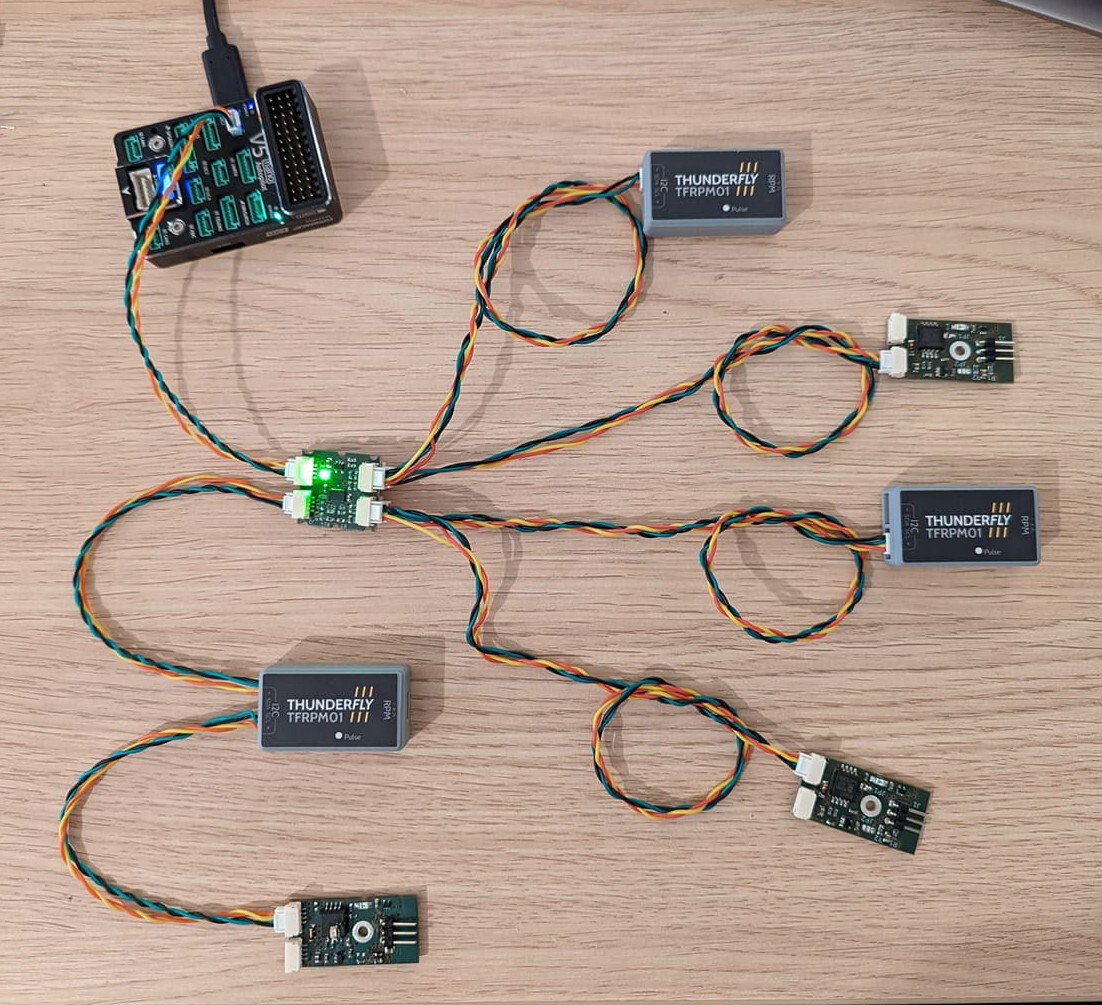
How many TFRPM01 sensors can I connect to the autopilot?
The TFRPM01D is a sensor that operates on the I2C bus, which requires a unique address for each device. The TFRPM01D itself allows setting 2 addresses. This way, you can connect a pair of TFRPM01 sensors to each I2C port.
If you use the TFI2CADT address translator, you can connect 6 TFRPM01 sensors to a single port (with one TFI2CADT). The TFI2CADT01 has two channels with different address translations. The configuration will then look as follows: TFRPM01 sensors without the case have their I2C address changed from 0x50 to 0x51.
It is then recommended to use an additional I2C port for the next 6 pieces, which will double the possible number of sensors, or to integrate another I2C translator (TFI2CADT) with different address translations into the structure.
So, you can connect quite a lot of TFRPM01 sensors to a single autopilot—far more than 6, 8, or even 12 units.
Does it connect to RPM output from ESC?
Generally, yes, the TFRPM could be connected to a revolution output from an ESC in case the output logic conforms to 5V TTL. The limitation is the RPM resolution here because many ESCs get one pulse per revolution. Please take a look at the formula above for an explanation.
Could be used for internal combustion engines?
Yes, it could measure the RPM of the IC Engine. However, it needs a pulse signal to count the rotation speed. The pulsed signal could be obtained either from Electronic control unit (ECU) or from an Optical or magnetic probe mounted on the proper location of the engine unit. Direct connection of TFRPM to ignition or sensing coils is not possible without signal conditioning, because the voltage of signals coming from coils will likely destroy the TTL-based RPM input of TFRPM. Required signal conditioning could be realized by a resistor network in many cases. Contact sale@thunderfly.cz in case you need professional support.