TFSLOT01 - Clogging-free airspeed sensor for low-speed UAVs
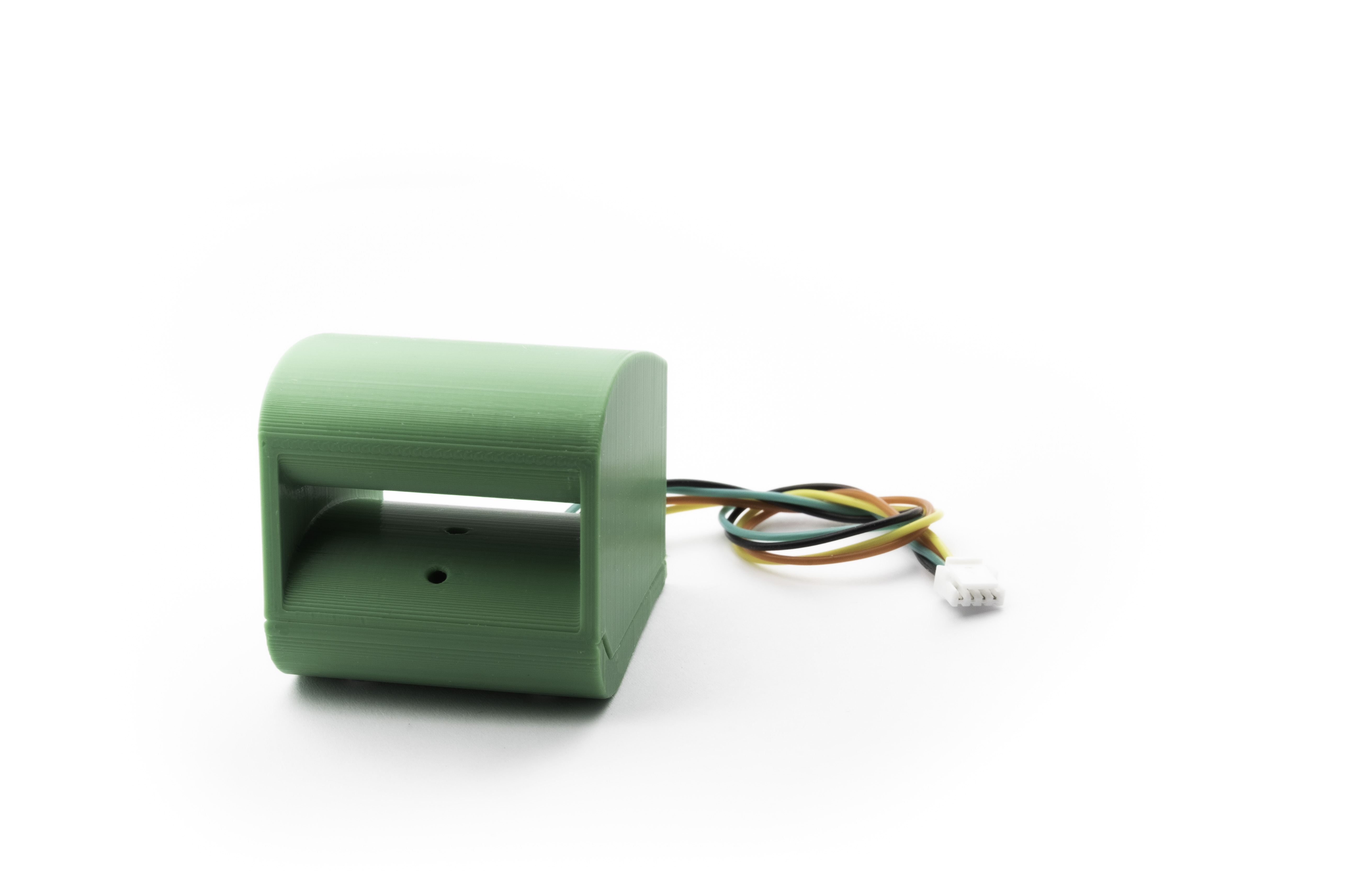
TFSLOT sensor is an airspeed sensor designed to be used on UAVs to measure IAS. Due to the 3D printed case, it is possible to optimize the characteristics according to the location of the sensor on the UAV and specific application requirements on measuring range. The first use of this sensor is on ThunderFly autogyro TF-G2.
TFSLOT01 was born out of a recurring failure we encountered with our TF-G1 and TF-G2 autogyros operating in real-world conditions. Standard pitot tubes kept clogging — mud and snow would pack into the stagnation port during low-altitude flight and landings in bad weather, causing airspeed to read zero at the worst possible moment. Every conventional fix we tried (covers, heating, flushing ports) introduced its own compromises. The root cause was the stagnation point itself, so we eliminated it entirely: TFSLOT01 uses the Venturi effect rather than direct impact pressure, meaning there is no port facing into the airflow for debris to enter. The fix proved very reliable in field conditions, and the sensor became standard equipment on TF-G2. For weight-critical platforms, its design later inspired the lighter TFPITOT01.
Main Features
- Improved low-speed resolution compared to traditional pitot tubes.
- Reduced tendency for clogging due to the absence of a stagnation point.
- Directly integrated differential pressure sensor, eliminating the need for additional tubing.
- Integrated magnetometer improves navigation reliability.
- Customizable 3D-printed case to fit specific applications.
- Integrated IMU for vibration diagnostics and AoA measurement.
How to Buy
- Direct order — Email sale@thunderfly.cz with your requirements for quotations or tailored configurations provided by ThunderFly s.r.o.
- Purchase TFSLOT01 on Lectronz for online orders.
Technical Parameters
| Parameter | Value | Description |
|---|---|---|
| Airspeed measurement range | 0 - 48 m/s | Assumes air density 1.29 kg/m³, negative airspeeds are also indicated but scaling is invalid |
| I2C Connector | 4-pin JST-GH | Pixhawk connector standard |
| I2C address | 0x21 SDP3x sensor, 0x68 IMU | SDP3x sensor is visible only after proper init of IMU |
| I2C SCL clock frequency | Typ. 400 kHz | Operation above 400 kHz is possible, but unreliable |
| Operating and storage temperature | −20°C to +40°C | Limited by case material |
| Operational input voltage | +3.6V to +5.4V | Overvoltage internally protected by Zener diode, Undervoltage is not treated |
| Mass | 25g | Using the 3D printed case gcode included |
| Dimensions | 35x40x35mm | Default 3D printed Case |
| Weather resistance | IP42 | External connectors fully occupied |
The TFSLOT uses the TFASPDIMU02 electronics, which has many more options for how it can be used. Please look at its documentation for more details and parameters. In cases where you need a lightweight Pitot Tube, the TFPITOT01 could be the better option.
Connection to the Pixhawk-based autopilots
The I²C interface connectors respect the Pixhawk connector standard. The signal and color coding of the connector and supplied cable are described by the following table (ThunderFly color scheme):
| Signal | Pixhawk Color | ThunderFly color |
|---|---|---|
| +5V | Red |  Red Red |
| SCL | Black |  Yellow Yellow |
| SDA | Black |  Green Green |
| GND | Black |  Black Black |
The cable’s conductor colors differ from the Pixhawk standard to increase the visual distinction between multiple cables in the UAV.
I2C Cable Twisting
To improve I2C bus reliability, the supplied cable is specifically twisted by following the scheme
- 10 turns for each pair SCL/+5V and SDA/GND per 30cm cable length
- The two pairs are turned again by 4 turns of pairs per 30cm cable length.
These special cable conductors’ winding method greatly improves the signal integrity by minimizing the crosstalk between the SDA and SCL signals.
Working Principle
The sensor uses the Venturi Effect to measure flight velocity in the air.

The velocity and pressure of the fluid are required to meet Bernoulli’s principle
Then the velocities are in relation to cross sections in the plane of the pressure measurement ports
Therefore, equations for pressure difference and airspeed velocity could be derived.
Where
| Symbol | Explanation |
|---|---|
| Measured pressure difference | |
| Air density | |
| Free air velocity e.g. measured airspeed | |
| The velocity of air running through the sensor | |
| Cross-section area at the position of the outer pressure port | |
| Cross-section area at the position of internal pressure port |
Comparison to pitot-static tube
In contrast to the classical Pitot tube, the TFSLOT design is the perfect choice for low airspeed measurement (generally below 10 m/s). The design has the following advantages compared to a pitot probe:
- Better resolution on low airspeeds (where kinetic pressure is small)
- Less tendency to clogging (due to the absence of a stagnation point)
- Direct differential pressure sensor integration without any additional tubing
The improved resolution on low airspeeds is the principal difference from the pitot-static tube. This could be explained by comparing it with the classical equation for the pitot-static tube:
The equation for the TFSLOT venturi-based sensor (see equations above) differs from it by a factor
That means the TFSLOT sensor is more sensitive (e.g., has a higher measurable pressure difference at the same airspeed) than the pitot-static tube (at the same air density) in every configuration where
The advantage of the higher sensitivity results in increased drag, but it could be negligible at low airspeeds. The best use case of the sensor is the integration of the sensing device into the relatively massive fuselage or other construction geometry. The user is supposed to find the best mounting option for the device or adapt the TFSLOT 3D printed case to fit the specific application. From that perspective, the TFSLOT01 is a fully functional development kit that can cover specific user needs.
Usage
TFSLOT is equipped with TFASPDIMU electronics, which contain the required differential pressure sensor (SDP33) and an IMU (ICM-20948) through which the pressure sensor is connected. To activate I2C access to it, it is necessary to set the pass-through mode in the IMU unit. The TFASPDIMU02 has many options for how it can be used. Please look at its documentation for more details.
PX4 flight stack
PX4 can initialize the sensor itself. All you have to do is add the following two lines to the startup configuration file on the Autopilot’s SD card.
icm20948_i2c_passthrough start -X -b 2 -a 0x68
sdp3x start -X
The script assumes a connection to port I2C 2. This was set by the -b parameter in both commands. The correct bus has to be set by the user.
The model for converting to the airspeed from an air pressure is not yet in the stable version of the PX4 autopilot source code. Therefore, the master upstream needs to be used with the sensor.
Sensor requires firmware with modifications from the tf/aspdimu branch. The GitHub pull-request into the PX4 master is currently open to solve this issue. The airspeed recalculation model should be included in the next stable release. Alternatively, you can temporarily apply this PR changes or apply patch.
Configuration
TFSLOT01 contains a specific aerodynamic profile. Therefore, it requires a different conversion model. This is done by setting the parameter CAL_AIR_CMODEL to 3 (Venturi effect-based airspeed sensor). Setting the wrong profile causes the measurement of negative airspeed values, which results in an airspeed sensor failure condition during the attempt to fly.
PX4 Calibration process

The sensor itself is calibrated, and the PX4 calibration process aims to verify that the sensor is properly mounted and connected. Thanks to the used sensor, this sensor is not sensitive to temperature changes and has zero offsets. It is enough to calibrate (verify) the sensor once it is mounted into the UAV. And there is no need to do it before each flight (as with other types of airspeed sensors).
The procedure is performed with the help of a calibration tool in a few steps:
- Place the calibration tool in the TFSLOT inlet
- Press the tool against the sensor (green arrow) with your hand or a rubber band and hold it there during the whole process.
- Start the calibration process in PX4
- Wait for the measure of static offset (no blowing)
- PX4 will command you to blow into the airspeed sensor
- Blow from the back of the sensor (blue arrow). If you blow too little, repeat the attempt.
- PX4 calibration should now be completed, confirmed by a beep, and in the QGC.

Ardupilot
The TFSLOT01 sensor uses standard ICs, which have driver support in ArduPilot, although for the use of airspeed sensing. The IMU (ICM-20948) must be set to pass-through mode.
FAQ
Is there a maximum altitude limit on the operation of the TFSLOT sensor?
There is no hard limit of maximum altitude to operate the TFSLOT01 sensor. However, the sensitivity of the sensor decreases with decreasing air density. Please take a look at the working principle description in the section above for a detailed explanation.