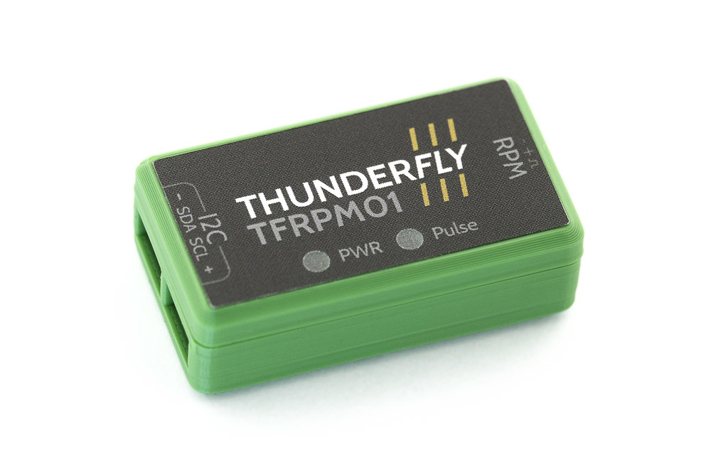
TFRPM01 - RPM measuring device
A revolutions per minute measurement device for a UAV. It is designed for direct connection to the Pixhawk controller (CUAV V5+, for example) through a standard I²C connector. The device is supported by PX4 firmware. The meter’s input is supposed to be a pulse signal from an optical encoder, hall sensor, etc. The pulses are counted during a predefined constant interval. The hardware is intended to measure helicopter and autogyro rotor RPM, but its counting capability is up to 20 kHz, so it should also be used to measure propeller or engine RPM.
TFRPM01 was created to solve a specific challenge in automating the launch of our TF-G2 autogyro (and the earlier TF-G1). An autogyro’s rotor must reach a minimum RPM before takeoff is safe — without rotor speed feedback, the autopilot is operating blind during the most critical phase of flight. We needed the autopilot to read rotor RPM reliably, but without tying the system to hardware-specific timer peripherals that differ between flight controller boards. An I²C counter was the clean solution: it offloads pulse counting to dedicated hardware and required only a single driver added to PX4, making the integration portable across all Pixhawk-standard autopilots.
Where to get it?
ThunderFly RPM counter is commercially available from ThunderFly s.r.o.. Write an email to sale@thunderfly.cz for direct orders, quotations, or custom requirements, or shop online at Lectronz.
Main Features
- Schmitt trigger input to shape a non-uniform signal from the RPM sensing element.
- Offloads the flight controller’s MCU by self-counting and storing the number of counted pulses in I²C-accessible internal memory
- Input status LED indicator - for easy debugging of the mechanical configuration
- Short circuit protection on the probe connector
- Pass-through I²C connectors to allow a daisy chain of additional or multiple sensors
- Highly robust and repairable design.
Parameters
| Parameter | Value | Description |
|---|---|---|
| Pulse frequency range | 0 - 20 kHz (equal high and low periods) | Maximum RPM value varies by pulse number per revolution |
| I2C Connector | 2x 4-pin JST-GH | Connected in parallel |
| RPM Pulse input connector | 3-pin 2.54mm pitch pin header | Internal 22k Ohm pull-up resistor |
| RPM Pulse input voltage range | 0-5V | Negative voltage or overvoltage could damage the input |
| RPM pulse input switching thresholds | +VT 1.88 V, -VT 1.12 V Typically@25°C | Hysteresis between VT+ and VT- is 0.756 V |
| I2C address | 0x50 default | By switching JP1, it is possible to change to 0x51 |
| I2C SCL clock frequency | Max 100 kHz | Operation on 400 kHz is possible, but unreliable |
| Operating and storage temperature | −20°C to +40°C | Limited by case material |
| Operational power voltage | +3.6V to +5.4V | Overvoltage internally protected by Zener diode, Undervoltage is not treated. Current consumption is defined mainly by the used probe. |
| Mass | 4g PCB + 8g case | Printed case gcode included in docs |
| Dimensions | 23.5x42x12.5mm / 37.5x19mm | Case / PCB |
| Weather resistance | IP40 | External connectors fully occupied |
The 3Pin probe connector is powered from the I²C bus through an RC filter, limiting current and voltage spikes to the sensor probe. Therefore, the sensor is resistant to short circuits at the probe connector power.
The two I²C Pixhawk JST-GH connectors are interconnected. This feature allows easy nesting with other I²C devices to a single Pixhawk I²C port.
Connection to the Pixhawk autopilot
The I²C interface connectors respect the Pixhawk connector standard. The signal and color coding of the connector and supplied cable are described by the following table (ThunderFly color scheme):
| Signal | Pixhawk Color | ThunderFly color |
|---|---|---|
| +5V | Red |  Red Red |
| SCL | Black |  Yellow Yellow |
| SDA | Black |  Green Green |
| GND | Black |  Black Black |
The conductor colors in the cable are different from the Pixhawk standard to increase the visual distinction between multiple cables in the UAV.
Wiring cable
To improve I2C bus reliability, the supplied cable is specifically twisted by following the scheme
- 10 turns for each pair SCL/+5V and SDA/GND per 30cm cable length
- The two pairs are turned again by 4 turns of pairs per 30cm cable length.
These special cable conductors’ winding method greatly improves the signal integrity by minimizing the crosstalk between the SDA and SCL signals.
I²C Address Configuration
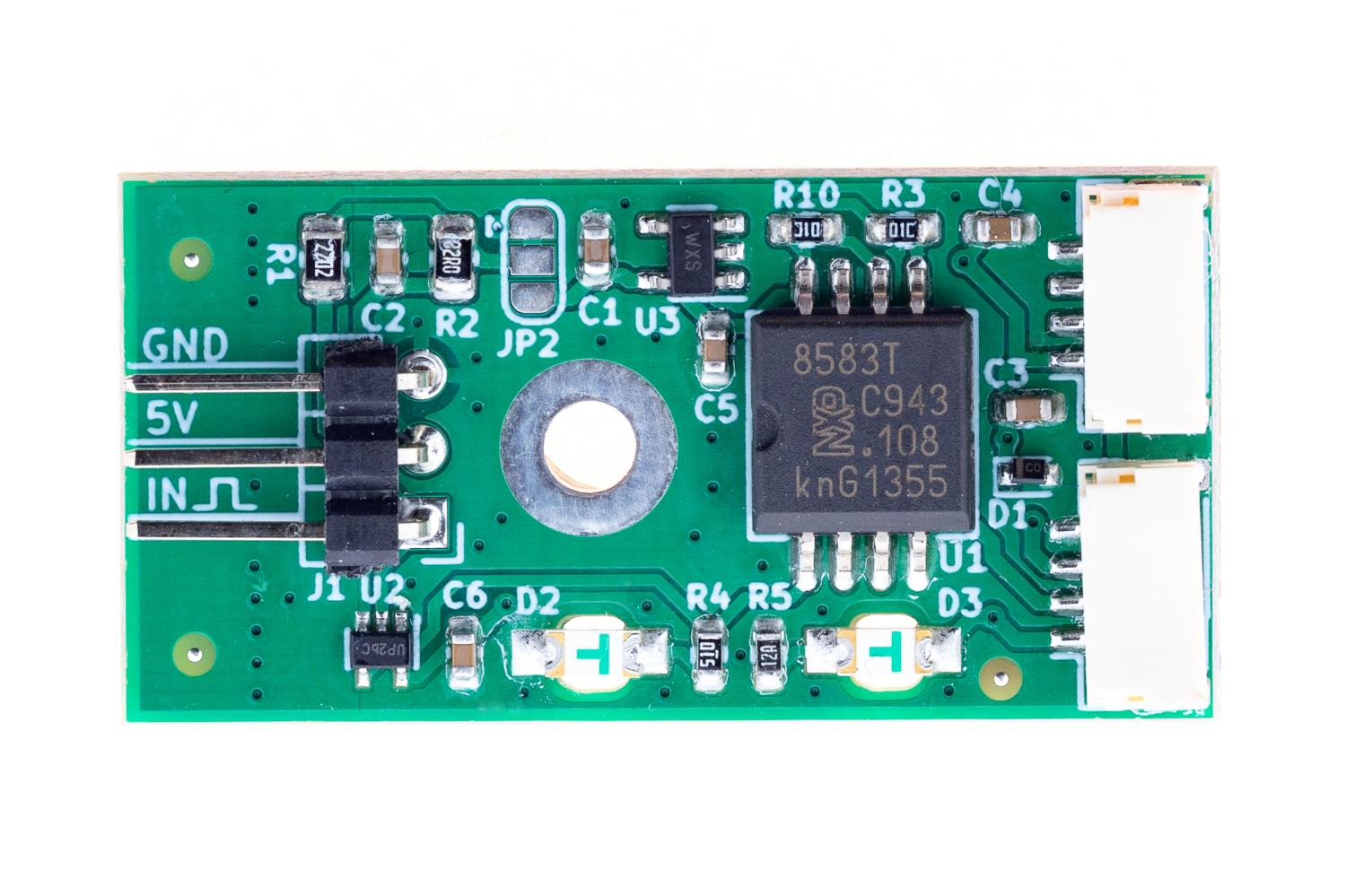
By default, the TFRPM01 sensor is manufactured with a 0x50 I²C address. This address is possible to change to 0x51 by altering the JP1 solder junction. The junction connection to GND needs to be cut with a knife and then soldered to the opposite side of Vcc. Then the PX4 driver could be started on an alternative I2C address by
pcf8583 start -X -b <bus number> -a 0x51
The default configuration of the junction corresponds to the following picture, where the center pin is connected to GND by a copper trace.

Mounting options
The device is designed to be mounted with or without a plastic case. The 3D-printed case is intended to be adjustable to particular sensor mount options. The supplied variant of the 3D-printed case supports two mount options:
- By default, the case could be mounted by the screw on a flat surface (the original screw needs to be replaced by a longer one)
- The second option is the use of double-sided adhesive tape or reclosable fastener stuck on the side of the TFRPM01 case.
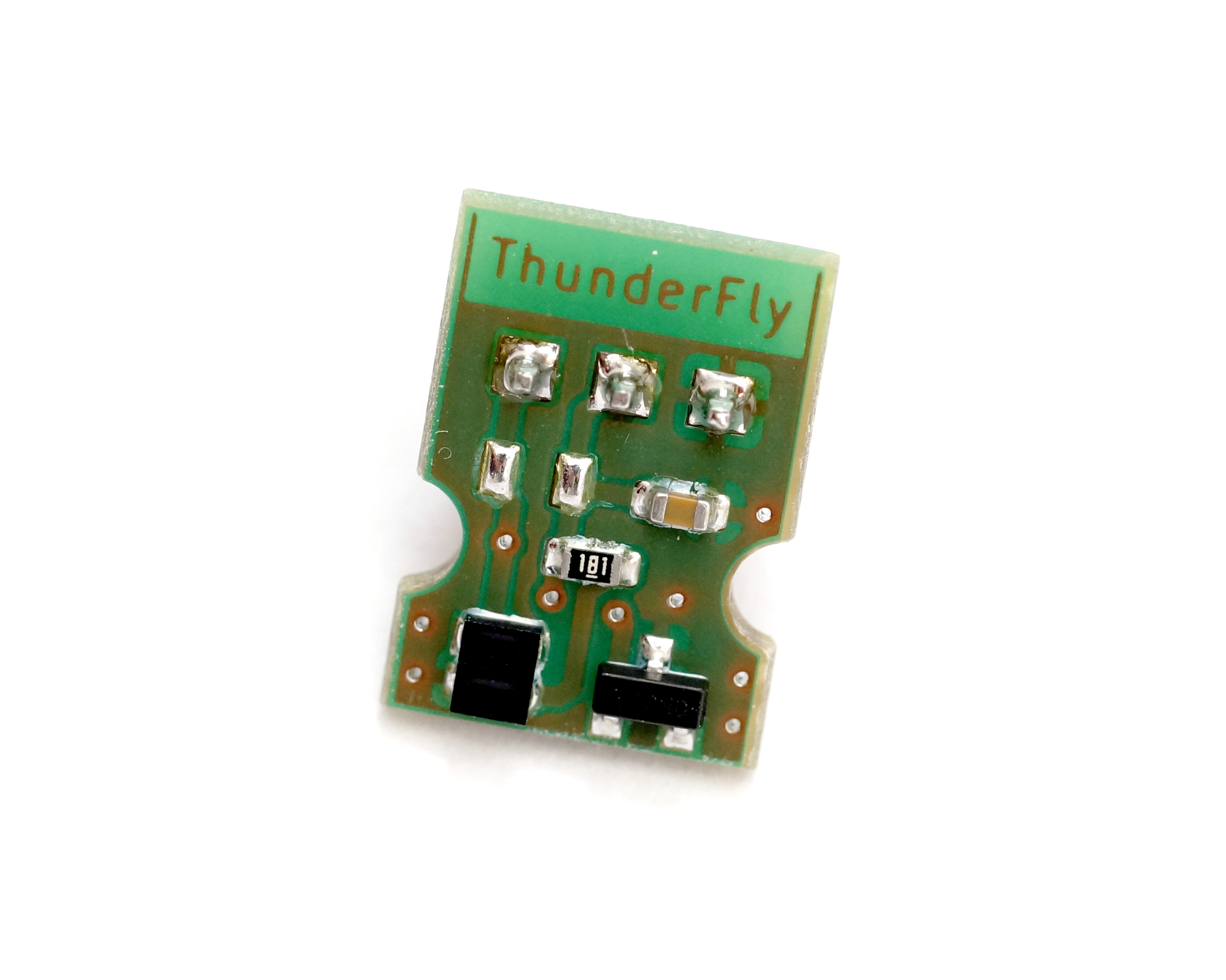
Sensor probe selection
The TFRPM01 can be used with multiple types of sensor probes. The most used one is a Hall effect probe. The magnetic probe is ideal for harsh environments, where dirt, dust, and water can contact the sensed rotor. The disadvantage is that magnet mounting is required for proper sensor work.
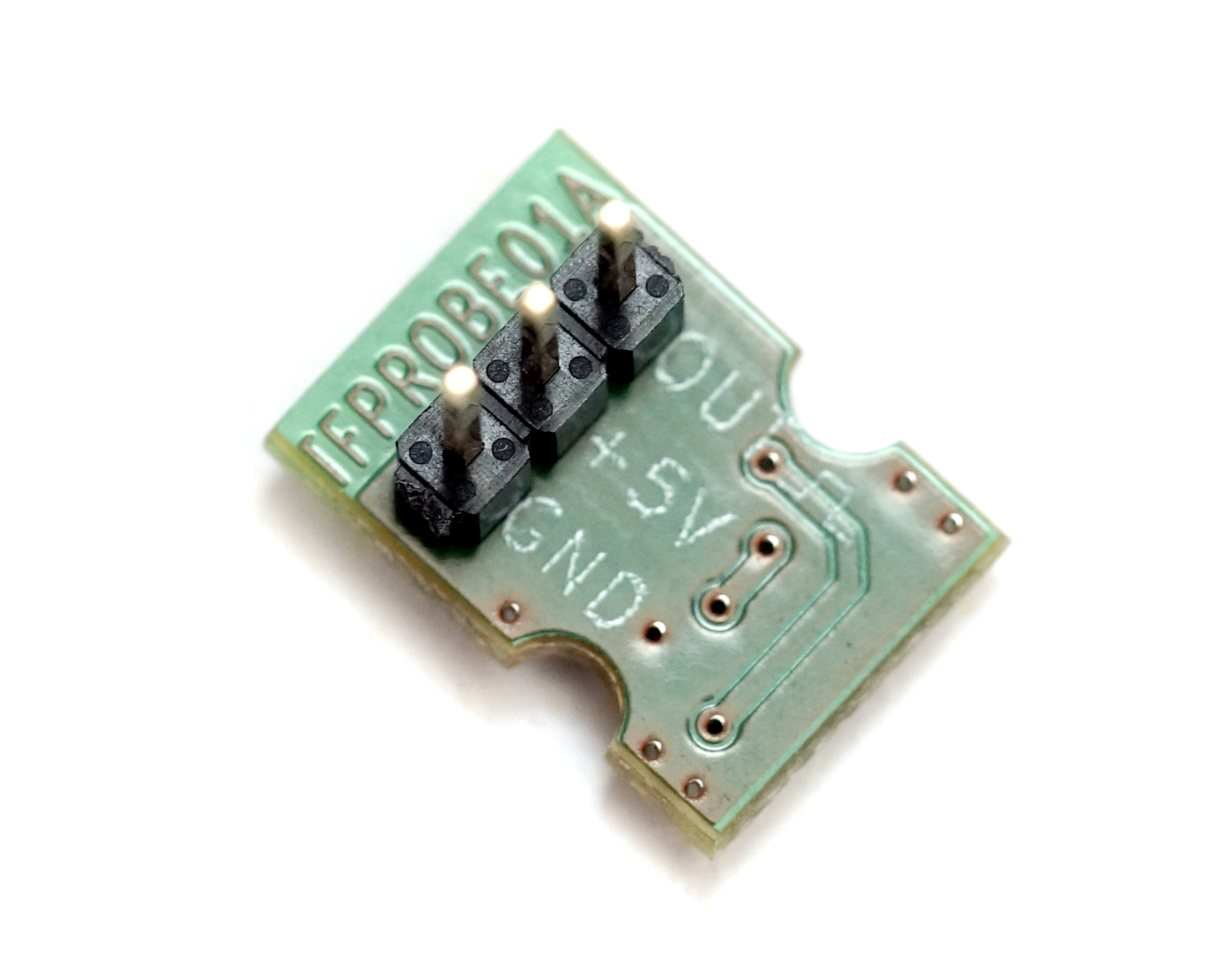
For more information on the options and selection of the appropriate probe, please take a look at the dedicated page Probe selection.
Software configuration
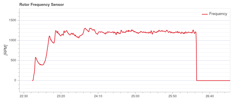
The TFRPM01 revolution counter is currently supported by PX4 firmware only. (Ardupilot pull requests are welcome) After proper connection of the sensor with the sensing probe to an I2C port (Except port I2C3) of the PX4-based autopilot, you should follow the instructions to PX4 software setup. After proper setup, you should get a uLog containing the RPM logged during the flight. Here is an example of rotor RPM captured during the flight of TF-G2 autogyro. The graph is rendered by flight_review.
FAQ
Frequently asked questions are available on separated TFRPM01 FAQ page.