TFSIK01 - High-Performance Telemetry Modem
Purchasing Information
The device can be purchased from ThunderFly s.r.o.. Contact us by email at sale@thunderfly.cz for a commercial quotation or shop directly from Tindie store or Lectronz marketplaces. We are the designers of this modem and therefore have full control of the modem’s construction and manufacturing. This gives us the ability to react even to non-standard requests for modification or functions by adopting our in-house European production.
Overview
The SiK Telemetry Radio is a small, light, and inexpensive open-source radio platform that typically allows ranges significantly better than one kilometer with a basic whip antenna kit. The range can be extended to several kilometers using a directional antenna on the ground. This radio is plug-and-play with all Pixhawk Standard and other flight controllers, providing the easiest way to set up a telemetry connection between the UAV and a ground control station. It uses open-source firmware specially designed to work well with MAVLink packets and to integrate with Mission Planner, Ardupilot, QGroundControl, and PX4 Autopilot.
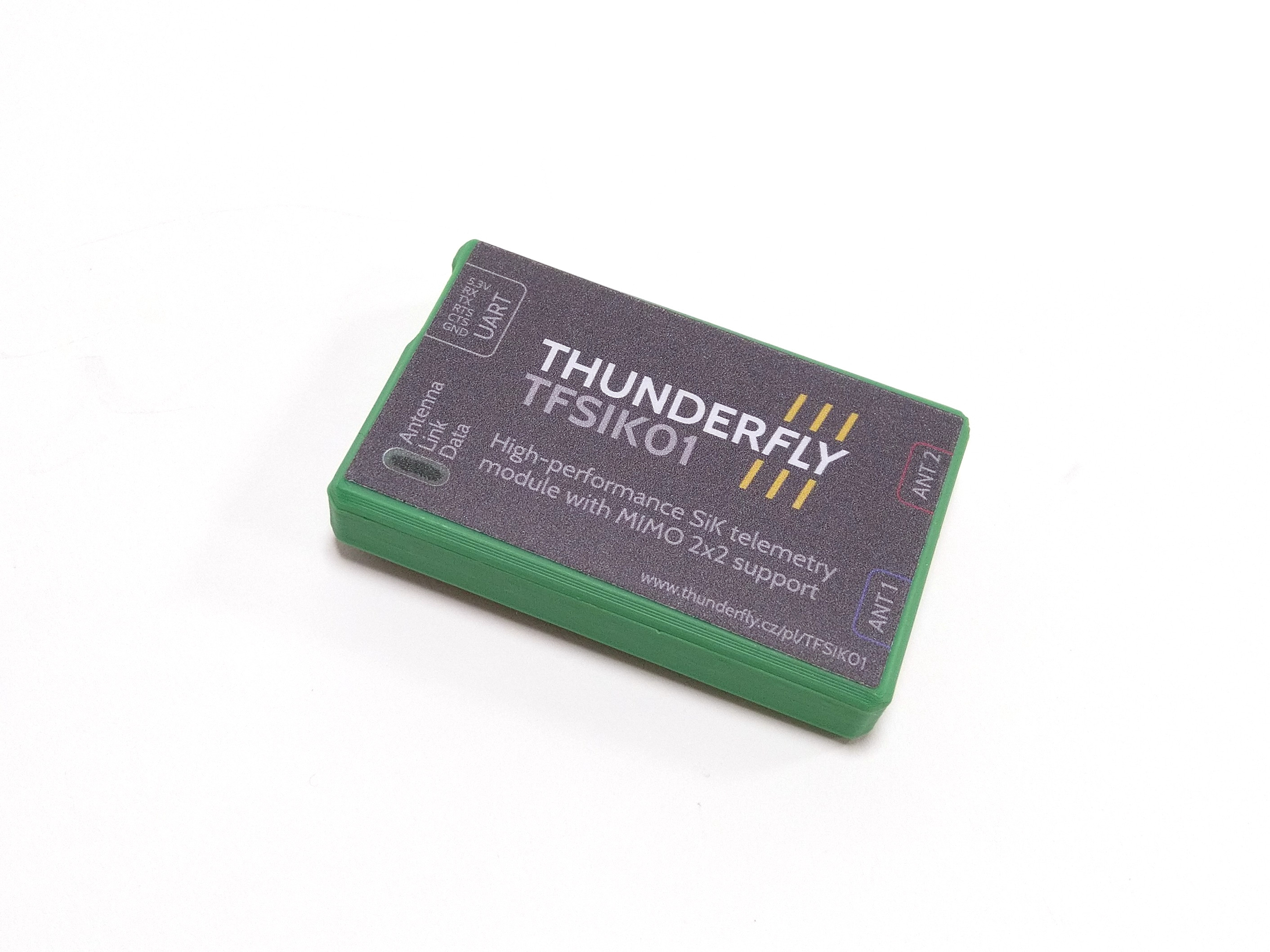
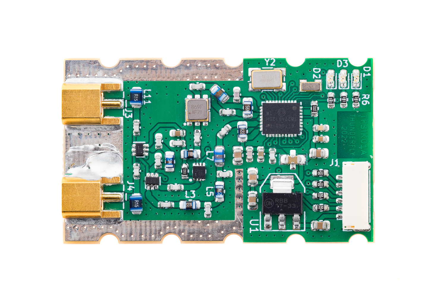
The TFSIK01 is a European-made state-of-the-art SiK-based unmanned vehicle C2 and telemetry modem incorporating dual antenna diversity and exceptional resistance to noise. This open-source hardware solution employs the advanced Si1060 chip from the Si10xx series and is further enhanced by the Si4463 EZRadioPRO transceiver, ensuring robust and secure communication capabilities. The modem’s design prioritizes immunity to interference from out-of-band frequencies, guaranteeing reliable performance in challenging environments and securing its position as a top choice for UAV systems that demand the utmost data integrity and security.
Key Features
- Plug-n-play for Pixhawk Standard Flight Controllers. The easiest way to connect your flight controller in the airframe to the Ground Station
- Superior Noise Immunity: With a hardware-optimized RF front-end, the modem excels in environments plagued by out-of-band signal interference. The feature applies to multiple frequency bands.
- Robust Hardware Design: Housed in a customizable 3D printed enclosure with electromagnetic shielding, it promises both durability and adaptability.
- Antenna Diversity: Employs dual external antennas via MCX connectors, enhancing connectivity flexibility across different frequency bands requiring different antenna systems.
- Cutting-Edge Communication Technologies:
- Implements Frequency-Hopping Spread Spectrum (FHSS)
- Utilizes Adaptive Time Division Multiplexing (TDM) with Configurable duty cycle
- Supports Listen Before Talk (LBT) and Adaptive Frequency Agility (AFA)
- Error correction corrects up to 25% of bit errors
- High-Performance Metrics:
- Offers a transparent serial link
- Facilitates air data rates reaching up to 250kbps
- Integrates MAVLink protocol framing and status reporting
- Achieves several kilometers of range with a small whip antenna
- Open-Source and Highly Configurable: Loaded with SiK firmware for enhanced customization through AT and RT commands, it supports the MAVLink 2 protocol, Configurable through Mission Planner & APM Planner
Hardware Parameters
| Parameter | Value | Description |
|---|---|---|
| Frequency range | 142 MHz - 1050 MHz | The Exact frequency band has to be set by the factory; commonly used bands are 433MHz, 868 MHz, and 915 MHz |
| RF power range | -20dBm to 20dBm (100 mW) | Adjustable by AT commands |
| Input Noise Figure | 0.6 dB | LNA noise figure |
| OIP3 | 39.5dBm | Input LNA gain 18.7dB |
| Receiver sensitivity | -117 dBm or better | Depends on datalink bandwidth configuration |
| Bandwidth | < 4 MHz | RF filter selective |
| RF connectors | MCX on both RF ports | snap-on function prevents damage of connector by extensive external forces |
| Serial interface | 3.3 V UART | 6-position JST-GH connector with handshake available |
| Operating and storage temperature | −20°C to +40°C | Limited by case material |
| Operational power voltage | +5V to +5.4V, 500mA max | Undervoltage is not treated. Current consumption is defined mainly by the set RF power. Receive current is 25 mA |
| Mass | 18g | Including the housing |
| Dimensions | 55x10x35mm | Housing dimensions |
| Weather resistance | IP40 | External connectors fully occupied |
For encryption or higher RF power, go to TFSIK02.
Frequency Band Specifications
Each TFSIK01 modem variant is hardware-optimized for a specific frequency band through RF front-end tuning. Operating outside the designated hardware-optimized band will result in significantly degraded RF performance. For optimal performance, range, and regulatory compliance, always use the modem variant specifically designed for your target frequency band. The table below shows frequency ranges for commonly used TFSIK01 band variants.
| TFSIK01 Band | Center Frequency | Applicable Frequency Range | Regional Allocation |
|---|---|---|---|
| 433 MHz | 434.0 MHz | 432.0 - 436.0 MHz | ISM band (worldwide) |
| 868 MHz | 869.0 MHz | 865.0 - 873.0 MHz | ISM SRD860 band (Europe) |
| 915 MHz | 915.0 MHz | 902.0 - 928.0 MHz | ISM band (Americas, Asia-Pacific) |
Notes:
- The exact frequency configuration is set during manufacturing and cannot be changed by the user
- Regional regulatory compliance must be verified before operation, while the modem hardware supports a wider bandwidth than the local regulations may allow within this range
- Custom frequency bands between 142-1050 MHz are available upon request
- Each frequency variant uses optimized SAW filtering for maximum selectivity and noise rejection
LEDs Indicators Status
The radios have 3 status LEDs: red, orange, and green
- Green LED blinking - searching for another radio
- Green LED solid - link is established with another radio
- Red LED flashing - transmitting data
- Red LED solid - in firmware update mode
- Orange LED solid or dim indicates the selected antenna port
Applications
The TFSIK01 is designed precisely for UAV command and control applications, ensuring dependable, long-distance communication links between UAVs and ground control stations. It is also highly effective in ROS2 environments for robotics, providing a reliable long-range wireless datalink.
The modem was originally developed to transmit atmospheric data measured in real time using the TF-ATMON system.
Installation and Configuration
Integration into UAV systems is straightforward, requiring only a Pixhawk-compatible JST-GH UART connection. The side placement of external antennas, connected through MCX connectors, is specifically selected to increase robustness and ease of installation.
Firmware Architecture and Configuration
The TFSIK01 modem is powered by SiK firmware, specifically optimized for long-range UAV telemetry applications. The firmware is designed to ensure high reliability even in noisy environments through the following mechanisms:
Communication Principles
The modem combines the following radio communication technologies:
Frequency-Hopping Spread Spectrum (FHSS): The operating frequency band is divided into discrete channels. The hopping pattern is randomized per
NETID, ensuring resilience against interference and channel collisions, and complying with regulatory limits.Adaptive Time Division Multiplexing (TDM): Each modem takes turns transmitting data in synchronized time slices to avoid collisions. Transmission timing is dynamically scaled based on data rate and buffer status.
Gaussian Frequency Shift Keying (GFSK): Provides spectral efficiency and reduced adjacent channel interference.
These features improve communication across various UAV deployment scenarios. The link dynamically balances itself if traffic is asymmetric, and clock synchronization is maintained using embedded timestamps in each transmitted packet.
Channel Allocation
To determine channel positions, the firmware uses the formula:
channel_width = (MAX_FREQ - MIN_FREQ) / (NUM_CHANNELS + 2)
Two guard channels on each edge of the frequency band ensure transmission stays within legal limits. Channels are further shifted based on the NETID to prevent cross-talk between neighboring systems.
Time Synchronization and Slot Management
Each modem sends 13-bit timestamps in its packets to stay synchronized with its peer. A complete TDM cycle includes:
- One modem’s transmit window
- A silence period (for channel switching and signal settling)
- The other modem’s transmit window
This ensures that only one side transmits at any moment, eliminating collisions. The default timing supports up to three full MAVLink packets per window. Lower latency can be achieved by reducing the MAX_WINDOW parameter.
Buffering and Flow Control
Data arriving over the UART is stored in a 2048-byte buffer. The radio firmware looks for MAVLink HEARTBEAT messages coming from the serial connection, and it injects its own MAVLink ‘RADIO’ status packets into the serial stream. These RADIO packets contain information about the RSSI level at both ends of the link, allowing the ground station or UAV to take action in case the link quality falls too low. The RADIO packets also contain information about error rates and how full the serial transmit buffer is (as a percentage). If enabled, hardware flow control can further optimize communication by removing the control symbols from UART data.
If the MAVLINK is to 2, then the radio will look for RC_OVERRIDE packets (used for joysticks) and ensure that those packets get sent as quickly as possible, in addition to doing MAVLink framing. That means the firmware will try to fit multiple MAVLink packets into one radio packet where possible for maximum efficiency. The longest possible radio packet size is 252 bytes. The firmware supports both the MAVLink 1.0 and the MAVLink 2.0 data formats.
Adaptive Slot Usage
If one modem has no data to send, it can yield its transmit slot to the other, improving throughput during unbalanced communication (e.g., more telemetry from UAV to GCS).
Configurable Parameters
The firmware supports runtime parameter configuration via AT commands. These parameters control how the modems communicate, how much power they transmit, and how they handle MAVLink framing and link reliability:
| Parameter | Description |
|---|---|
| Baud (default 57) | The rate at which the mission planner or vehicle communicates with the local radio. “57” = 57600 bits per second. Must match the serial port settings on both ends. |
| Air Speed (default 64) | The rate at which the two radios communicate. It is the rate in kbps, truncated to an integer. “9” = 9600 baud, “38” means 38400, “64” = 64kbps, “115” = 115200, etc. Lowering this rate increases range but reduces data throughput. |
| ECC (default is “0” off) | Controls whether error correction is used. When on, 12/24 Golay error correction is applied, adding a 16-bit CRC. This theoretically improves reliability but halves throughput. Has minimal benefit in the case of MAVlink framed data. |
| MAVlink (default is “1” (MAVLink) | Optimizes transmission for MAVLink packets. Set to 2 “Low Latency” if using a joystick or tablet control. RSSI and error rates are only sent in MAVLink mode. For general data set to “0” |
| Tx Power (default 20) | Transmission power in dBm. Should comply with local regulations. |
| Duty Cycle (default 100) | Max % of time the radio transmits. A lower duty cycle may enable higher transmit power or broader frequency access (e.g., <10% in the EU). Bandwidth decreases with lower duty cycles. A duty cycle of 0 means receive-only mode. |
| Max Window (default 33) | The interval (in ms) within which the GCS can send a packet. Lower values like 33 reduce latency, especially in “Low Latency” mode. |
| LBT Rssi (default 0) | RSSI threshold for Listen Before Talk (LBT). If >0, the radio waits for a quiet channel before transmitting. Formula: signal_dBm = (RSSI / 1.9) - 127. Example: 25 = -121 dBm. Required for compliance in some regions. Minimum listen time is 5ms, with randomized delay per EU rules. |
| RTS CTS | Enables RTS/CTS hardware flow control. Can be set to “auto” to optimize performance. |
You can query and set these values using AT commands over the serial interface.
Using AT Commands
To configure the modem, you may access the command interface via a serial terminal (e.g., picocom, minicom):
picocom /dev/ttyUSB0 -b 57600
+++   # wait 1 second before and after typing
OK
ATI5  # show all parameters
To change a parameter:
ATS4=14   # set Tx power to 14 dBm
AT&W      # write to EEPROM
ATZ       # reboot
Some useful commands:
ATI1– Firmware versionATI5– List all parametersATSx?/ATSx=val– Get/set specific parameterAT+P=x– Set Tx power immediatelyAT+L– Lock bootloaderAT+A=1|2– Override antenna selection (specific to TFSIK01)
The full list of commands is maintained in the firmware documentation.
Range Optimization
To achieve optimal range and performance with the TFSIK01 modem, it is essential to understand and configure the firmware parameters that influence the radio link. The following subsections guide adjusting key parameters such as data rate, duty cycle, and physical link geometry.
Choosing the Air Data Rate
The AIR_SPEED parameter is the primary factor controlling the range and throughput of the telemetry radio. Lower values result in a longer range but reduced data throughput.
Supported air data rates (in kbps): 2, 4, 8, 16, 19, 24, 32, 48, 64, 96, 128, 192, 250
Typical configuration tips:
- Long range, low data requirement: Use AIR_SPEED 4 or 8
- Medium range, moderate data: Default 64 offers a good compromise
- High throughput, short range: Use 192 or higher
Note: If an unsupported rate is selected, the closest higher supported rate is used by the firmware instead.
Duty Cycle Setting
The DUTY_CYCLE parameter defines the maximum percentage of time the modem is allowed to transmit radio signals. The default setting is 100%, meaning the modems can transmit almost continuously if required. However, reducing this value can be beneficial or even necessary under certain regulatory or operational conditions:
- Regulatory compliance: In some regions (e.g., the EU), lower duty cycles (typically under 10%) allow the use of higher transmission power or access to a broader frequency band without the need for special licenses.
- Noise mitigation: Lowering the duty cycle can reduce interference in densely used radio environments by making the transmission “bursty”.
- Receive-only mode: Setting
DUTY_CYCLEto 0 disables transmission, allowing the modem to operate in passive listening mode. That works only for lowNUM_CHANNELS, otherwise the clock synchronisation will be poor.
While reducing the duty cycle may reduce the average throughput, the modem can still maintain effective telemetry, since telemetry traffic is often bursty in nature. For example, even with a 10% duty cycle, reliable MAVLink telemetry is possible at 2 Hz using a medium AIR_SPEED.
Noise, Bandwidth & Channel Planning
The TFSIK01 modem mitigates interference by frequency hopping across a user‑defined number of channels NUM_CHANNELS while Time‑Division Multiplexing (TDM). The two design choices directly affect the efficiency of this technique:
Air data rate (
AIR_SPEED) ⇒ occupied channel bandwidth. An approximation used in SiK isBW_channel ≈ 1.2 · AIR_SPEED (in kHz)Example: 64 kbps ⇒ ≈ 77 kHz occupied bandwidth. 250 kbps ⇒ ≈ 300 kHz.
Number of hopping channels (
NUM_CHANNELS). The usable spectrum betweenMIN_FREQandMAX_FREQis divided into equal slices. Each slice should be wider thanBW_channelplus guard space; otherwise, adjacent channels overlap and frequency-hopping will be inefficient.
| AIR_SPEED (kbps) | Approx. BW_channel | Safe NUM_CHANNELS in 1.8 MHz band (433 MHz example) |
|---|---|---|
| 16 | ≈ 20 kHz | up to 50 |
| 64 (default) | ≈ 77 kHz | 10–25 (default = 10 gives wide guard bands) |
| 128 | ≈ 154 kHz | 8–10 |
| 250 | ≈ 300 kHz | ≤ 5 |
The table assumes the common 433.05–434.79 MHz sub‑band (≈ 1.74 MHz wide) used in EU ISM regulations. For other bands calculate available width accordingly and choose NUM_CHANNELS so that (MAX_FREQ − MIN_FREQ)/(NUM_CHANNELS+2) ≥ BW_channel The “+2” allows for guard channels.
Additionally, to correct the use of frequency hopping. The noise sources need to be reduced to allow effective use of every possible radio channel:
- Place antennas away from wideband EMI sources (motors, ESCs).
- Use shielded USB cables and an externally powered USB hub on the ground station to reduce computer‑generated noise.
Every 6 dB of extra fade margin roughly doubles the coverage distance.
Link Budget
A link budget is a systematic accounting of gain and loss between the transmitter and the receiver. It could predict whether the received signal will still exceed the receiver‑sensitivity (plus a chosen fade‑margin) after free‑space path loss, antenna gains, cable losses, and other impairments. For a more detailed overview, see the link budget.
The simplified formula used throughout this guide is:
P_rx = P_tx + G_tx + G_rx − L_fs − L_misc
| Symbol | Meaning | Example value |
|---|---|---|
| P_tx | Transmit power (dBm) | 20 dBm (Regulatory maximum) |
| G_tx | Transmit‑side antenna gain | 2 dBi (433 MHz) / 3 dBi (868 MHz) |
| G_rx | Receive‑side antenna gain | Same as G_tx (symmetrical setup) |
| L_fs | Free‑space path loss (dB) | Depends on distance and frequency |
| L_misc | Miscellaneous losses (cable, connectors, fading) | Typically 2‑5 dB (not included in simple examples below) |
The receiver sensitivity of the TFSIK01 is ≈ −117 dBm at 64 kbps. For a reliable link, we target ≥ 10 dB fade margin, so the maximum usable path loss is:
L_fs(max) ≈ P_tx + G_tx + G_rx − (P_sens − 10) ≈ P_tx + G_tx + G_rx + 107
433 MHz band
- Frequency (f): 433 MHz
- Antenna gain: 2 dBi
- Transmit power (P_tx): 20 dBm
- Target line‑of‑sight distance (d): 10 km (LOS)
Free‑space path loss (FSPL):
L_fs = 32.44 + 20·log10(d_km) + 20·log10(f_MHz)
     = 32.44 + 20·log10(10) + 20·log10(433)
     ≈ 105 dB
Received power:
P_rx = 20 + 2 + 2 − 105 ≈ −81 dBm
Fade margin:
Margin = P_rx − (P_sens) ≈ −81 − (−117) ≈ 36 dB
A 36 dB margin is ample; even after subtracting 10–15 dB for multipath and other losses, the link should remain solid at 10 km.
868 MHz band
- Frequency: 868 MHz
- Antenna gain: 3 dBi
- Transmit power: 20 dBm
- Target distance: 10 km LOS
L_fs = 32.44 + 20·log10(10) + 20·log10(868)
     ≈ 111 dB
Received power:
P_rx = 20 + 3 + 3 − 111 ≈ −85 dBm
Fade margin:
Margin ≈ −85 − (−117) ≈ 32 dB
Even at the higher 868 MHz frequency, the margin comfortably exceeds the suggested 10 dB.
Maximum LOS Range (theoretical)
Re‑arranging the FSPL formula gives an estimate of the maximum line‑of‑sight distance d_max (km) when the fade margin is set to 10 dB:
d_max = 10^((P_tx + G_tx + G_rx − (P_sens − 10) − 32.44 − 20·log10(f_MHz))/20)
Using the same parameters:
| Band | Antenna gain | d_max (ideal LOS) |
|---|---|---|
| 433 MHz | 2 dBi each | ≈ 195 km |
| 868 MHz | 3 dBi each | ≈ 123 km |
Fresnel Zone Constraints and Antenna Height
A radio link is only truly “clear line‑of‑sight” if most of the first Fresnel zone is unobstructed. Objects intruding into this ellipsoidal volume add extra path‑loss and drastically shorten range.
The radius r (m) of the first Fresnel zone at distance x on a link of length d is
r ≈ √( λ·x·(d−x) / d ) where λ = c / f
At the worst‑case mid‑point (x = d/2):
r_mid ≈ 8.7 · √( d_km / f_GHz )
| Band | rmid at 10 km | rmid at 20 km | rmid at 50 km |
|---|---|---|---|
| 433 MHz | ≈ 42 m | ≈ 60 m | ≈ 94 m |
| 868 MHz | ≈ 29 m | ≈ 42 m | ≈ 65 m |
A common engineering guideline is to keep ≥ 60 % of this radius clear ideally along the entire path.
In the case of 433 MHz link and ground antenna 2 m AGL, UAV at 100 m AGL, target distance 20 km.
- First Fresnel radius @ 20 km: ≈ 60 m → 60 % clearance required ≈ 36 m.
- Straight‑line LOS height at mid‑path ≈ (h_g + h_u)/2 = (2 m + 100 m)/2 ≈ 51 m.
Clearance margin = 51 m − 36 m ≈ 15 m → seemingly acceptable. However, even a gentle hill only 40 m high in the middle of the path will cut through the Fresnel zone, adding ≥ 10 dB excess loss and destabilising the link. If the UAV descends to 50 m AGL, LOS at mid‑path drops to 26 m, which is definitely below the required 36 m. The link will now fade or drop entirely, despite high RSSI, in the case of higher flight. If the ground antenna is raised to 10 m → LOS mid‑height (10 + 50)/2 = 30 m, restoring clearance and link.
That is why high‑altitude platforms and missions provide almost complete Fresnel clearance, which is why TFSIK01 has achieved hundreds of kilometres range in stratospheric balloon tests.
Hardware setup
Like most RF devices, the TFSIK01 must not be operated without a properly connected and matched antenna. Doing so can damage the RF output stage.
The basic TFSIK antenna kit
External antennas are connected to the TFSIK modem by a pair of MCX connectors. For ease of use, we prepared a kit with simple whip antennas. These kits are available for multiple frequency bands; 868 MHz is shown here as an example. Each antenna kit must be used only with a TFSIK modem tuned to the same frequency band, otherwise RF performance will be severely degraded.
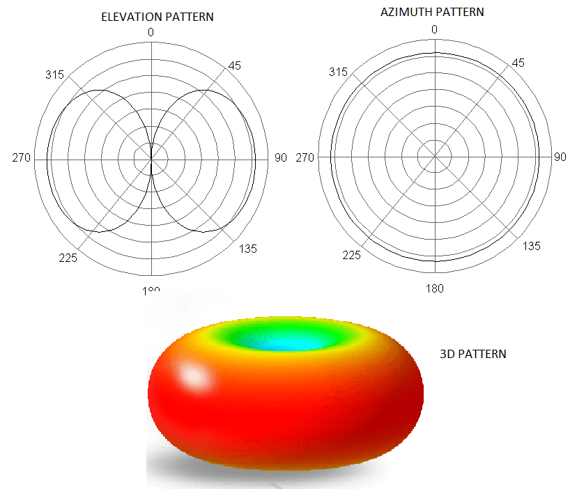
Two mechanically different variants of the antenna kit are available, optimized for different use cases. The both antenna kits are mounted to the flat surface using two screws through the mounting holes. The each antenna kit contains two antennas. The optimal installation depends on your exact setup, but generally, the antennae should be orthogonal to each other due to the “donut” radiation pattern of the each antenna.
UAV variant (vibration-resistant)
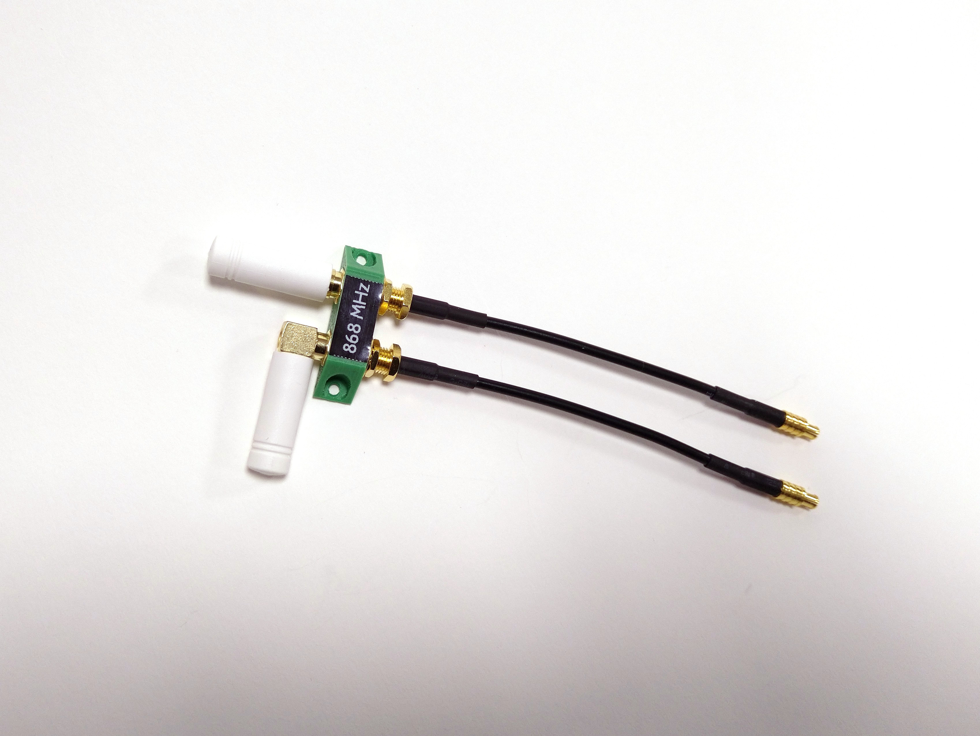
The UAV antenna kit is intended for airborne applications where vibrations and mechanical shocks are present. In this variant, the SMA connectors of both antennas are secured using lock nuts, which prevents the connectors from loosening during flight due to vibration.
GCS variant (quick-reconfigurable)
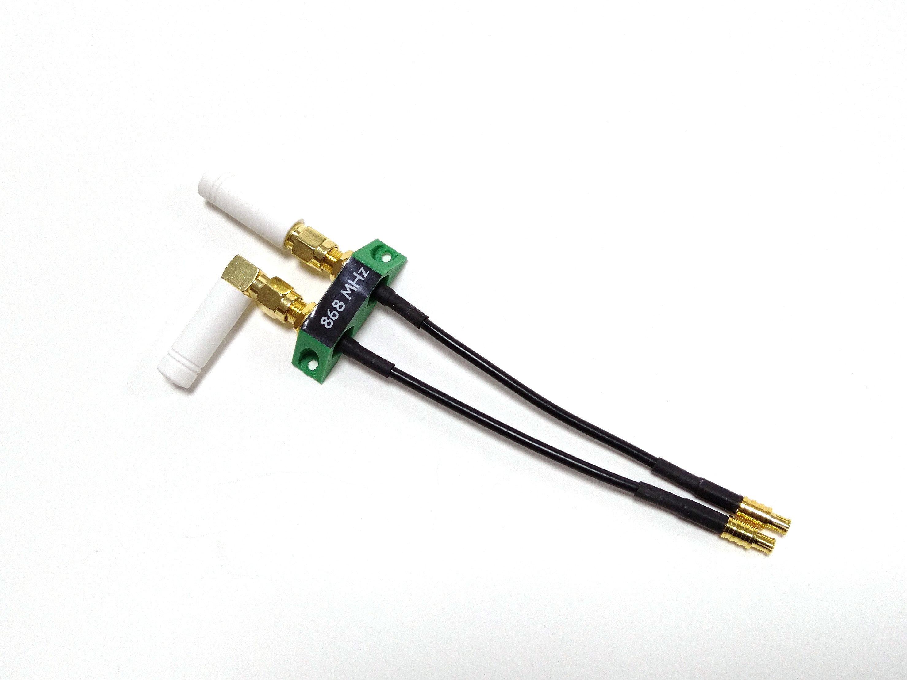
The GCS (Ground Control Station) antenna kit is optimized for stationary use where vibrations are negligible. In this variant, the SMA connectors are not mechanically locked, allowing the antennas to be easily loosened, repositioned, or replaced without tools.
Connecting to Autopilot
Connection to the autopilot flight controller is facilitated through a JST-GH cable with a 6-pin connector. While PX4 firmware initially configures the TELEM1 port for telemetry connections, adjustments in the PX4 or Ardupilot firmware settings allow for modem connections through any available UART port.
Ground Station Connectivity
Direct UART Connection
The TFSIK01 modem directly interfaces with ground stations via its UART port, enabling easy integration with Raspberry Pi or similar single-board computers equipped with 3.3V UART outputs. This direct connection method is ideal for configurations demanding low latency and direct data control.
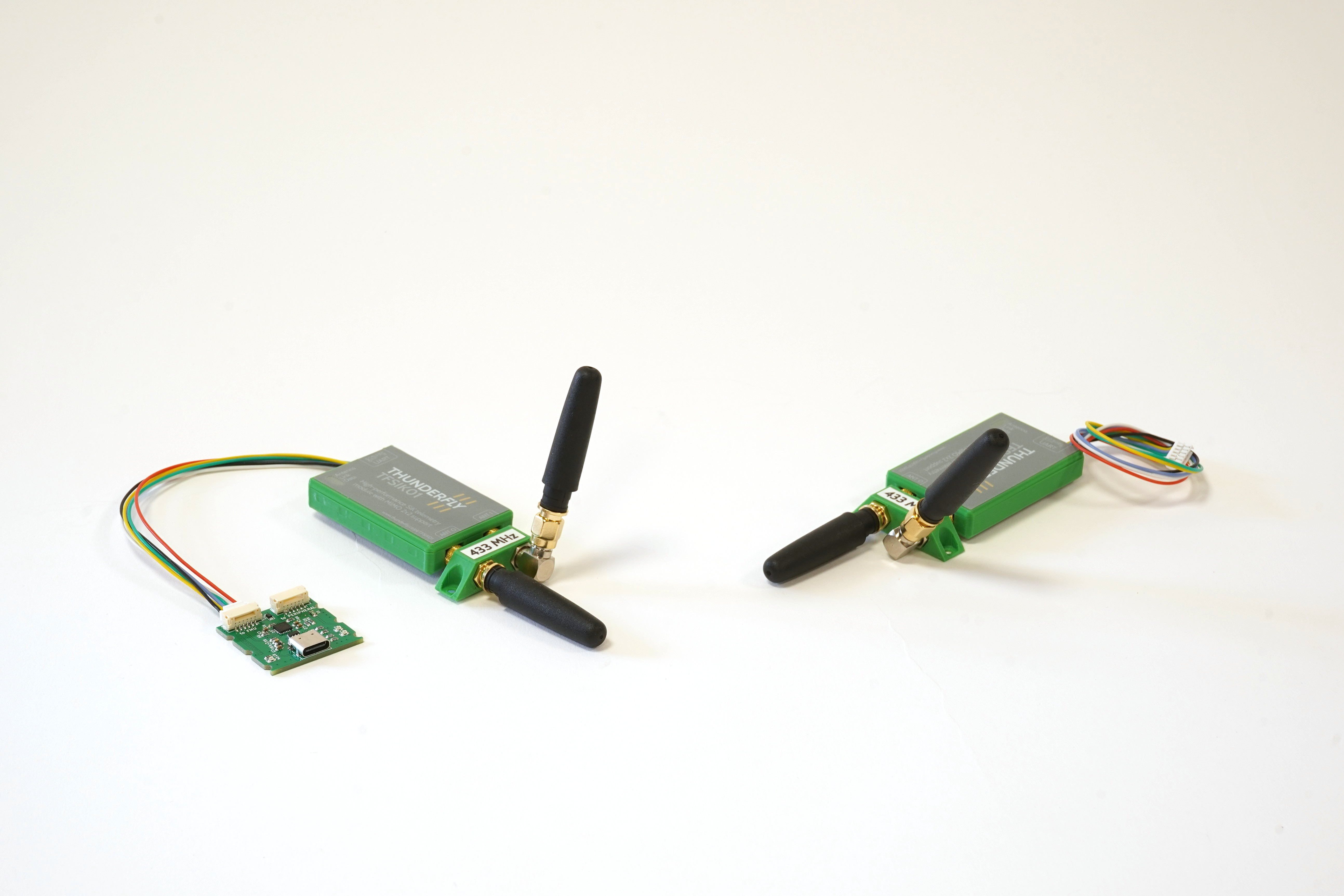
USB Connectivity
To connect the modem to a computer, a USB to UART conversion is essential. The TFUSBSERIAL01 module, specifically designed for this purpose, features an FTDI-based USB chip for reliable data transmission and includes a USB-C connector for easy linking to computers or mobile devices, alongside a UART JST-GH connector for straightforward connection to the TFSIK01 modem.
Frequency Options
ThunderFly typically configures the TFSIK01 modem for the 433 and 868 MHz bands. For alternative frequency requests, ThunderFly can customize the modem to meet specific applications. For detailed information on frequency adjustments, contact ThunderFly directly at sale@thunderfly.cz.
Always verify the modem’s compliance with local regulations and laws concerning frequency and transmitting power for operation before use. Confirm the necessity for any operational permissions or licenses within your jurisdiction.
FAQ
Could I increase RF output power above 20 dBm?
The power limit conforms to civil use-cases for military and defense applications, go for TFSIK02.
How can I connect it to a PC/mobile/tablet?
The easiest solution is the use of TFUSBSERIAL01 gadget to create a virtual UART/Serial link from a USB-A or USB-C connector.
How can I update the firmware?
Download the latest firmware release and flash it to the TFSIK01 by using the following command:
python3 uploader.py --port /dev/ttyUSB0 radio~tfsik01a.ihx
Use the correct serial port path for your system (e.g., /dev/ttyUSB1 or COM3).
Brick Recovery: Forcing bootloader mode
In case the device becomes unresponsive due to a corrupted or incompatible firmware (e.g., incomplete upload or incorrect image), it is possible to manually enter bootloader mode:
- Power off the modem.
- Short the CTS and GND pins on the modem’s UART connector (6-pin JST-GH). (Using tweezers is a good option)
- If you’re using the TFUSBSERIAL01, these pins are accessible on the JST-GH connector after removing the enclosure.
- Power on the modem while keeping the short in place.
- The LED should remain solid, indicating that the modem is in bootloader mode.
- Remove the short between CTS and GND once programming begins.
- Run the firmware upload command as usual.
This procedure bypasses normal startup and allows recovery even if the modem firmware fails to boot properly.
How can I monitor the link quality?
The SiK modem firmware provides telemetry signal strength data (RSSI) that can be visualized in real-time in Ground Control Station software such as Mission Planner, QGroundControl, or post-flight from logs using PlotJuggler. The following link parameters are reported:
- Local RSSI: signal strength received by the local modem.
- Remote RSSI: signal strength received by the remote modem.
- Local Noise: The noise floor is being received in the aircraft.
- Remote Noise: The noise level being received on the ground.
The Remote and Local mean from the modem side of view. Therefore, the remote is a UAV modem if viewed from GCS, and also, the ground modem is remote from the point of view of the UAV modem. The Remote and Local are exchanged in GCS and flight logs.
Monitoring both values provides insight into the quality and symmetry of the communication link, as is demonstrated in the following graph. As seen in the figure, the signal strength for TFSIK01 decreases almost smoothly with increasing distance, making it easier to predict link performance and diagnose issues caused by interference or configuration problems.
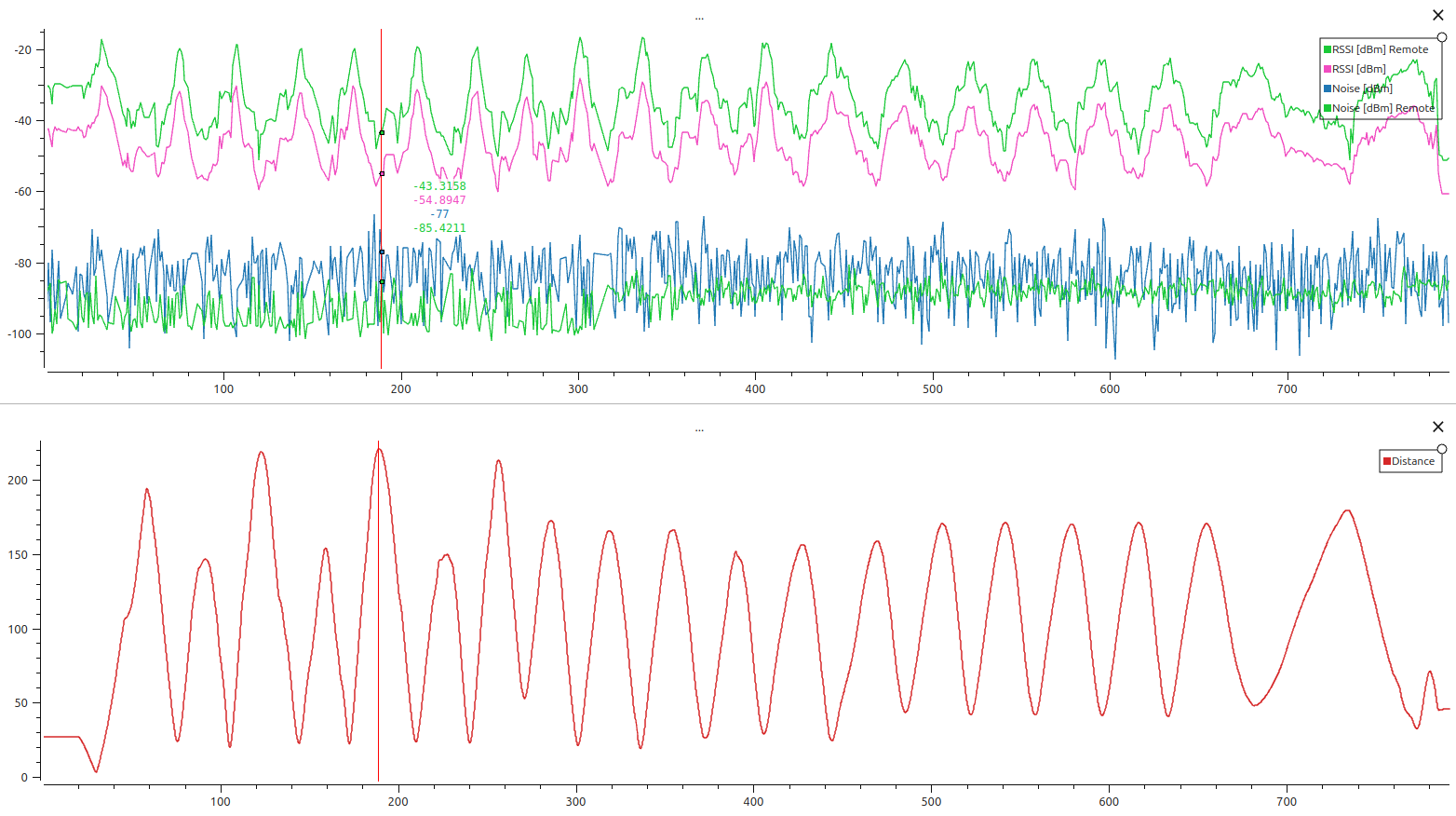
Thanks to the dual antenna diversity system, the TFSIK01 maintains stable signal levels even when the UAV changes orientation. Unlike conventional modems, where antenna directionality causes fluctuations, the TFSIK01 switches between two antennas to maintain the best signal. The used PlotJuggler layout could be downloaded here.
A reliable telemetry link depends not only on received signal strength (RSSI) but also on the link signal-to-noise ratio (SNR) because the link could be degraded due to background noise. This is because the effective SNR (RSSI – Noise) becomes too small for reliable demodulation, and basically, if the RSSI and background noise level (Noise) meet in the graph, the radio link is lost.
The recommended minimum SNR for a reliable MAVLink connection is approximately 10 dB. If the noise level increases (due to interference or hardware issues), the same RSSI may no longer be sufficient.
The figure above shows both RSSI and Noise values from both ends of the link. If you encounter packet loss or poor range despite good RSSI values, examine the corresponding noise measurements.
If SNR is consistently insufficient, consider:
- Reducing interference: improve RF shielding and move away modem and antenna from EMI emitting devices such as power supplies, or switching regulators.
- Lowering the air data rate: slower rates improve link robustness and increase receiver sensitivity.
- Using directional antennas (especially on the ground side) to improve gain and reject side noise.