TFRPM02 - RPM Measuring Device
The TFRPM02 is a compact RPM sensor for UAVs designed for direct connection to Pixhawk-class autopilots via the standard I²C port. It is the second-generation successor to the TFRPM01, sharing the same operating principle — a pulse-counting I²C counter IC — while adopting the unified ThunderFly avionics form factor and a smaller PCB footprint.
The sensor accepts a pulse signal from an external sensing probe (optical encoder, Hall-effect sensor, etc.). Pulses are counted by the on-board I²C counter and read out periodically by the flight controller. The TFRPM02 uses the same PX4 pcf8583 driver as the TFRPM01.
Where to Buy?
The TFRPM02 is available from ThunderFly s.r.o..
For a quotation or support, contact us at sale@thunderfly.cz.
Main Features
- Schmitt trigger input — shapes noisy or slow-edge signals from Hall-effect or optical probes
- I²C counter offloading — the PCF8593 counts pulses autonomously, freeing the autopilot MCU
- Status LED — one pulse per revolution for easy mechanical verification
- ThunderFly form factor — 25 × 20 mm PCB, compatible with TF carrier boards and stacking
- Overvoltage protection — 5.6 V Zener clamp on the probe supply line
- Internal 3.3 V LDO — runs from the standard 5 V Pixhawk I²C bus
Technical Specifications
| Parameter | Value | Description |
|---|---|---|
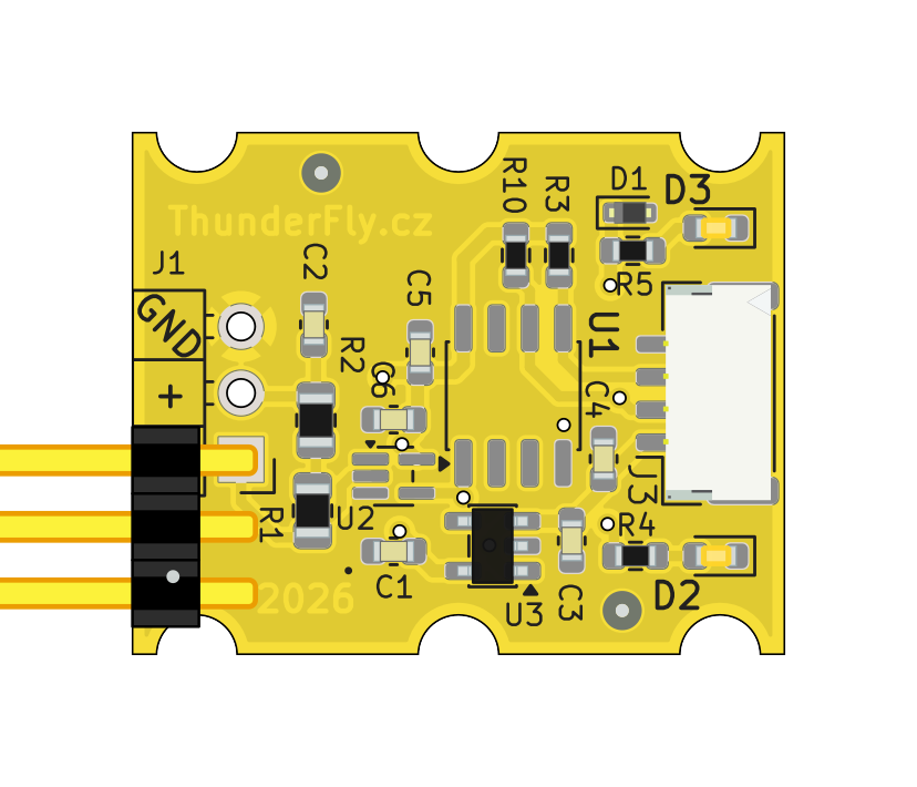
| Signal conditioning | 74LVC1G14 Schmitt trigger | Single-channel inverting Schmitt trigger |
| I²C address | 0x50 (default) | Changeable to 0x51 via JP2 solder jumper |
| I²C SCL frequency | Max 100 kHz | |
| Input voltage | 3.6 – 5.4 V | Standard Pixhawk I²C bus voltage |
| Probe supply | 3.3 V via LDO | On-board MIC5504-3.3 LDO; probe supply filtered and protected |
| Probe pull-up | 22 kΩ | Internal pull-up to 3.3 V on probe signal line |
| I²C connector | JST-GH 4-pin | Pixhawk standard pinout |
| Probe connector | 3-pin 2.54 mm header | Same pinout as TFRPM01 |
| PCB dimensions | 25 × 20 mm | ThunderFly avionics form factor |
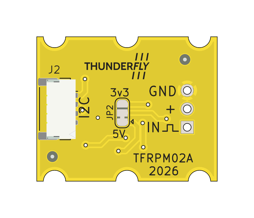
Pin Configuration
I²C Connector (JST-GH 4-pin)
Interface conforms to the Pixhawk Connector Standard.
| Pin | Name | Type | Description |
|---|---|---|---|
| 1 | VCC | Power | +5 V from autopilot |
| 2 | SCL | Input | I²C clock |
| 3 | SDA | I/O | I²C data |
| 4 | GND | Ground | Ground |
Probe Connector (3-pin 2.54 mm header)
| Pin | Name | Description |
|---|---|---|
| 1 | VCC | Probe supply (3.3 V from LDO) |
| 2 | SIGNAL | Pulse input with 22 kΩ pull-up to 3.3 V |
| 3 | GND | Ground |
I²C Address Configuration
The default I²C address is 0x50. The address can be changed to 0x51 by modifying the JP2 solder jumper: cut the default bridge between pads 1–2 and solder pads 2–3.
After changing the address, the PX4 driver must be started with the -a 0x51 argument (see below).
PX4 Autopilot Integration
The TFRPM02 is supported by the PX4 pcf8583 driver.
Enabling the Driver
Set the SENS_EN_PCF8583 parameter to 1 in QGroundControl or via the MAVLink console, then reboot:
param set SENS_EN_PCF8583 1
After reboot the driver starts automatically on the external I²C bus at address 0x50.
Manual Start via Console
To start the driver manually from the PX4 NSH console:
pcf8583 start -X -a 0x50
Where -X selects the external I²C bus and -a 0x50 is the default I²C address. To verify:
pcf8583 status
To stop:
pcf8583 stop
Driver Parameters
| Parameter | Default | Unit | Description |
|---|---|---|---|
SENS_EN_PCF8583 | 0 | — | Enable driver: 0 = disabled, 1 = enabled. Requires reboot. |
PCF8583_POOL | 1 000 000 | µs | Sensor poll interval. Requires reboot. |
PCF8583_RESET | 500 000 | counts | Counter reset threshold. The internal counter resets when this value is reached; lower values improve accuracy at the cost of more frequent resets. Requires reboot. |
PCF8583_MAGNET | 2 | counts/rev | Number of pulses per revolution from the probe. Must match the number of magnets or encoder slots. Requires reboot. |
For more details on software setup and data interpretation, refer to the PX4 ThunderFly tachometer documentation.
Sensor Probe Selection
The TFRPM02 is compatible with the same probes as the TFRPM01. The most common choice for UAV applications is a Hall-effect probe used together with a small magnet mounted on the rotating part. Optical probes (reflective or transmissive) are also supported.
For probe selection guidance, see the TFRPM01 probe selection page.
Differences from TFRPM01
| Feature | TFRPM01 | TFRPM02 |
|---|---|---|
| PCB size | 37.5 × 19 mm | 25 × 20 mm |
| I²C connectors | 2× JST-GH (pass-through) | 1× JST-GH |
| Power supply | Direct 5 V | 5 V with on-board 3.3 V LDO |
| Form factor | Custom | ThunderFly standard |
| PX4 driver | pcf8583 | pcf8583 (same) |
Applications
- Helicopter and autogyro rotor RPM monitoring
- BLDC motor speed feedback
- Propeller and engine RPM measurement
- Any pulse-output rotary speed sensor application